


Overview
Hardware Specifications
| Parameter | Specification |
|---|---|
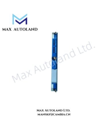
| Model | 125720-02 |
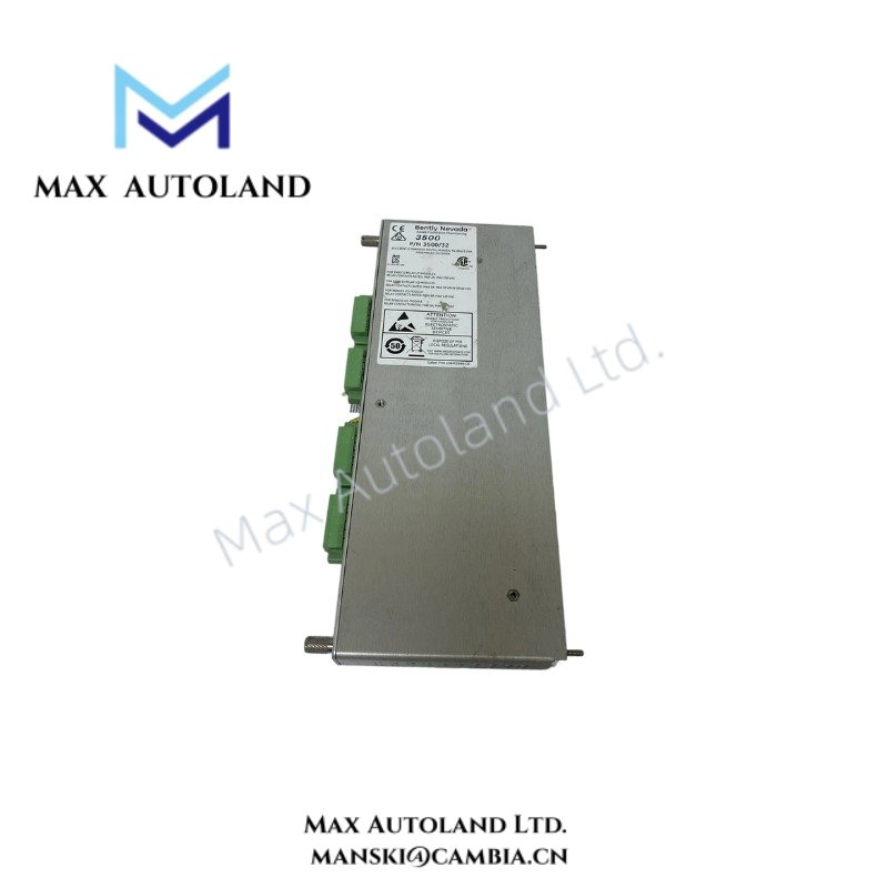
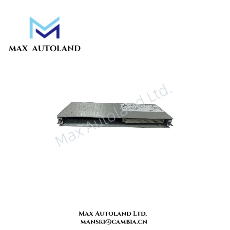
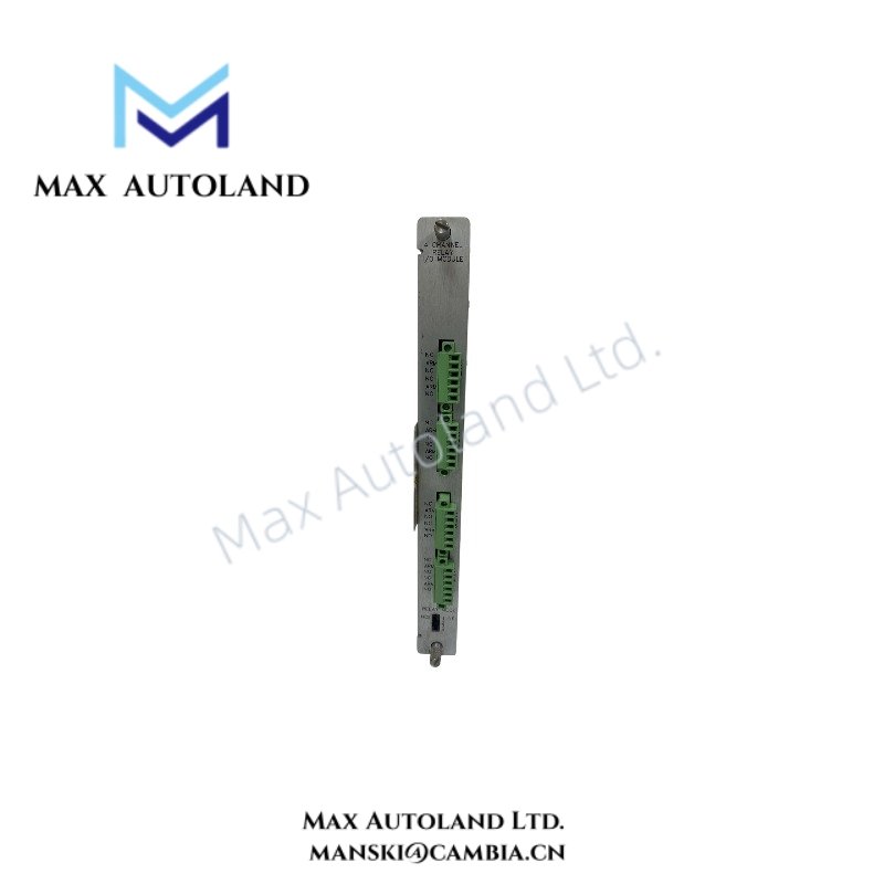
| Product Series | Bently Nevada 3500/32 |
| Product Type | Spare 4-Channel Relay Output Module |
| Brand | Bently Nevada |
| Manufacturer | Bently Nevada |
| Origin | USA |
| Weight | 0.45 kg |
| Dimensions | 2.3 x 11 x 24 cm |
| Operating Temp | -40 deg C to +85 deg C |
| Humidity | 0-95% RH, non-condensing |
| Power Consumption | Not specified in the provided technical data |
| Module Height | Full-height module |
| Relay Outputs | 4 independently programmable outputs |
| Maximum Switched Current | 2 A per channel |
| Maximum Switched Power | 450 VA |
| AC Contact Rating | 30 VAC, 2 A maximum, resistive load |
| DC Contact Rating | 30 VDC, 2 A maximum, resistive load |
| Logic Functions | AND and OR logic |
| Alarm Inputs | Alert, Danger, Not-OK, and individual PPLs |
| Configuration | Bently Nevada 3500 Rack Configuration Software |
| Rack Installation | Slots to the right of the Rack Interface Module |
| Replacement Model | 125720-01 |
Mechanical Monitoring Alarm Logic and Rotor Dynamics
The 125720-02 does not directly perform eddy-current probe scaling. Instead, it receives configured alarm and protection states generated by monitor channels within the 3500 rack and converts the programmed logic result into physical relay contact operation.
For machinery protection applications, relay logic can combine Alert, Danger, Not-OK, and individual PPL conditions from monitor channels. Consequently, the output logic can support external shutdown or annunciation circuits associated with rotor dynamics and machinery condition monitoring.
The module also supports independently programmed voting logic for each relay output. Therefore, one relay can respond to a single monitor condition while another relay can require an AND or OR combination of multiple monitor channel states.
Where gap voltage validation is configured through compatible proximity monitoring channels, the commonly referenced -10 VDC target condition remains part of the monitor signal evaluation process rather than a direct measurement function of the 125720-02 relay module.
Frequently Asked Questions
Q: Can all four relay outputs use different alarm logic?
A: Yes. Each of the four relay outputs can be independently programmed to perform the required voting and Alarm Drive Logic.
Q: What alarm conditions can be used in the relay logic?
A: The configured Alarm Drive Logic can use Alert and Danger statuses, Not-OK conditions, individual PPLs, or combinations of monitor channel conditions within the rack.
Q: Can the 125720-02 directly measure proximity probe gap voltage?
A: No. The module is a relay output device. Probe signal processing and gap voltage evaluation are performed by the applicable monitoring channels, while the 125720-02 operates according to configured alarm logic.
Field Installation Guidelines
Install the 125720-02 in a compatible full-height slot located to the right of the Rack Interface Module, following the applicable 3500 rack configuration requirements.
Before installation, isolate rack power and verify that the relay wiring corresponds to the configured load voltage and current limits. Do not connect a load exceeding 2 A per relay channel or the stated contact ratings.
Route relay output wiring separately from low-level transducer and monitor input circuits where practical. This arrangement helps reduce electrical coupling between switching circuits and machinery monitoring signals.
Verify external circuit grounding and shielding according to the overall control panel design. In addition, inspect terminal connections for correct polarity and load assignment before energizing the rack.
After installation, configure each relay output using the Bently Nevada 3500 Rack Configuration Software. Finally, perform functional testing of the programmed Alert, Danger, Not-OK, PPL, AND, and OR logic before placing the connected protection circuit into service.

Reviews
There are no reviews yet.