

Overview
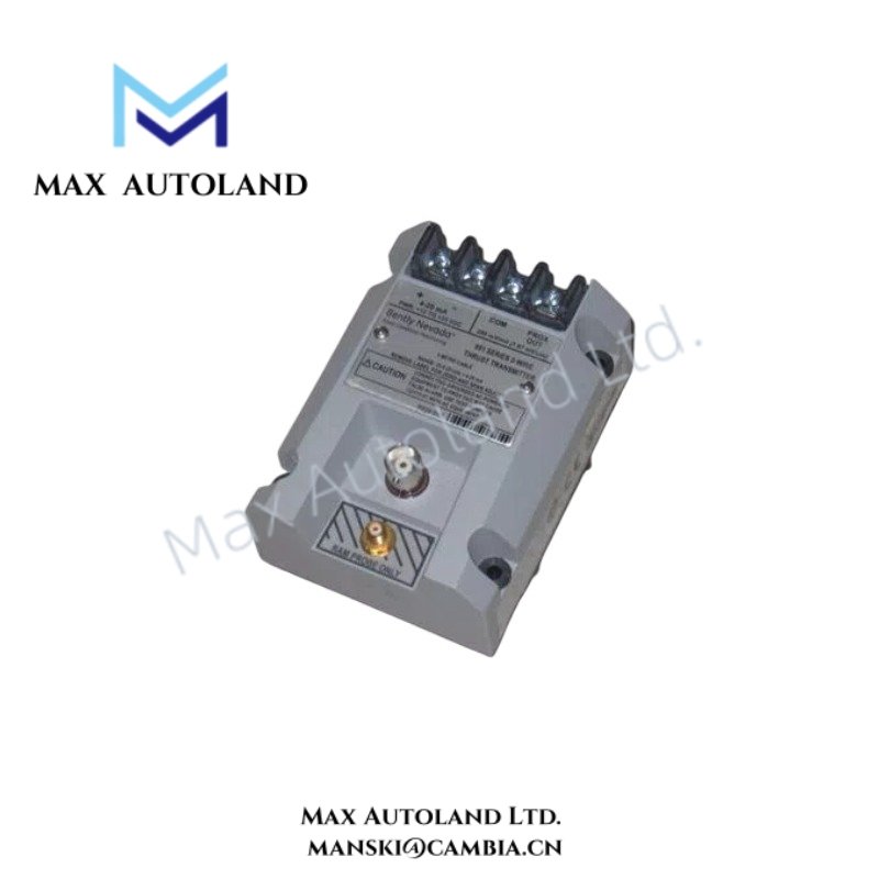
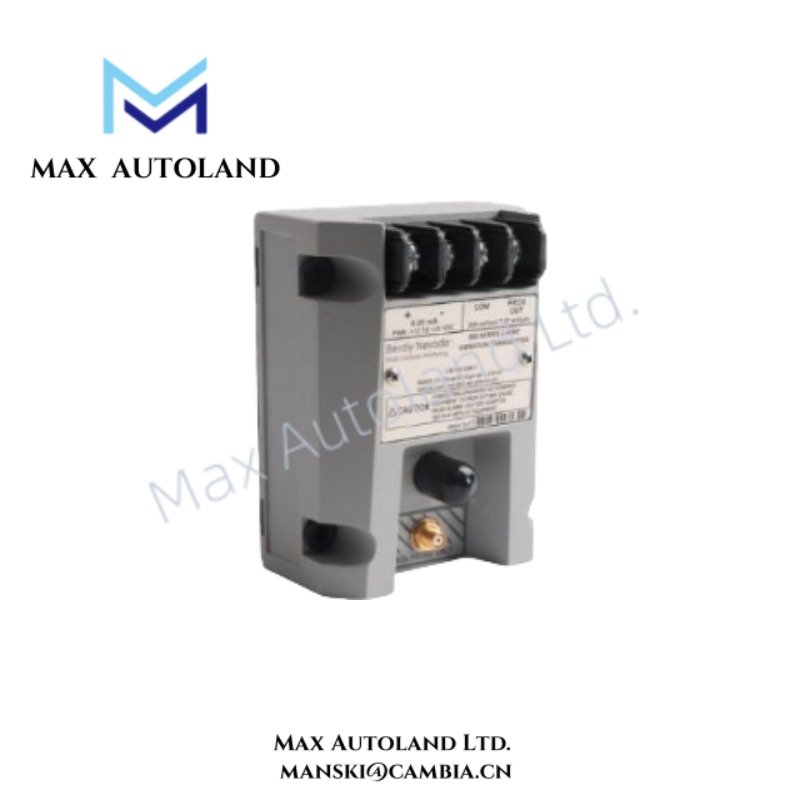
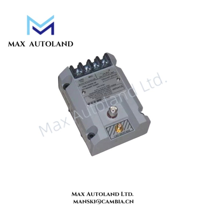
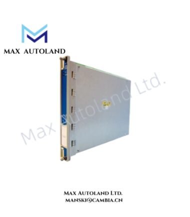
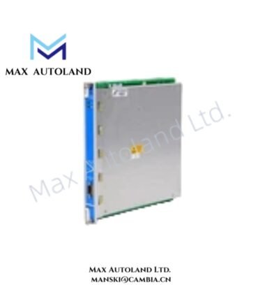
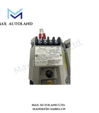
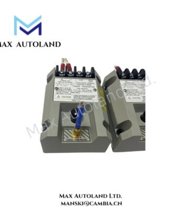
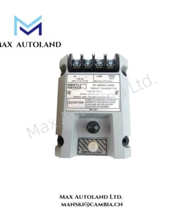
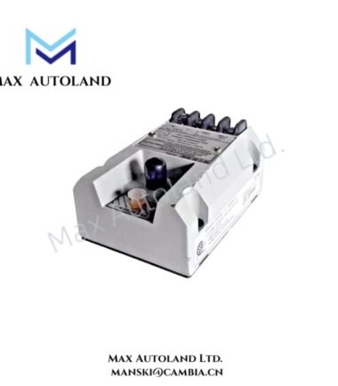
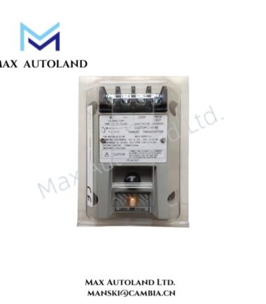
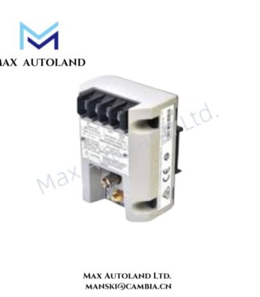
The Bently Nevada 991-01-XX-01-00 MOD: 288865-01, also cataloged as the 991 Thrust Transmitter, converts thrust position signals from compatible mechanical monitoring hardware into a transmitter output for continuous machinery monitoring. The unit accepts +12 to +35 VDC at the transmitter terminals and supports 5.0 m or 7.0 m system length options.
Hardware Specifications
| Parameter | Specification |
|---|---|
| Model | 991-01-XX-01-00 MOD: 288865-01 |
| Base Model | 991 |
| Product Type | Thrust Transmitter |
| Brand | Bently Nevada |
| Manufacturer | Bently Nevada |
| Origin | USA |
| Weight | 0.5 kg |
| Dimensions | 10 x 7.4 x 6 cm estimated shipping size |
| Operating Temp | -35 deg C to +85 deg C |
| Power Consumption | +12 to +35 VDC input at transmitter terminals |
| Current Limiting | 23 mA typical |
| System Length Option | 5.0 m or 7.0 m |
| Mounting | 35 mm DIN-rail clips |
| Agency Approval | Not required |
| Shipment Origin | Xiamen, China |
| Tariff Code | 8537101190 |
Thrust Measurement and Rotor Dynamics
The 991 Thrust Transmitter processes thrust-position signals associated with rotating machinery monitoring. It provides the electrical interface between the measurement circuit and the downstream monitoring or control system.
The specified 5.0 m and 7.0 m system length options define the available system configuration. Therefore, technicians should match the transmitter configuration with the installed probe and cable arrangement.
For Bently Nevada machinery monitoring systems, technicians should also verify probe scaling and gap voltage before commissioning. Where an eddy-current proximity measurement chain is used, the installation team should confirm the probe target condition and validate the expected negative DC gap-voltage relationship before placing the measurement loop into service.
Frequently Asked Questions (FAQ)
Q: What supply voltage does the 991-01-XX-01-00 require?
A: The transmitter requires a +12 to +35 VDC input applied at the transmitter terminals.
Q: What mounting method does this configuration specify?
A: This configuration specifies 35 mm DIN-rail clips for mechanical mounting.
Q: What system length options are specified for this model?
A: The supplied configuration information specifies 5.0 m and 7.0 m system length options.
Field Installation Guidelines
- Install the transmitter on a compatible 35 mm DIN rail using the specified mounting clips.
- Verify the DC supply polarity and confirm that the available supply remains within the specified +12 to +35 VDC range.
- Route signal wiring separately from high-current power conductors, contactors, and other high-noise circuits where practical.
- Maintain proper cable shielding and connect the shield according to the plant instrumentation grounding scheme.
- Verify the selected 5.0 m or 7.0 m system length against the installed measurement circuit before commissioning.
- For eddy-current probe installations, check probe wiring, target clearance, and gap-voltage behavior before enabling machinery protection functions.
- Confirm the transmitter output at the receiving monitor or control input before placing the measurement channel into operational service.
- Record the installed model, configuration, wiring arrangement, and commissioning measurements in the maintenance documentation.


Reviews
There are no reviews yet.