
Overview
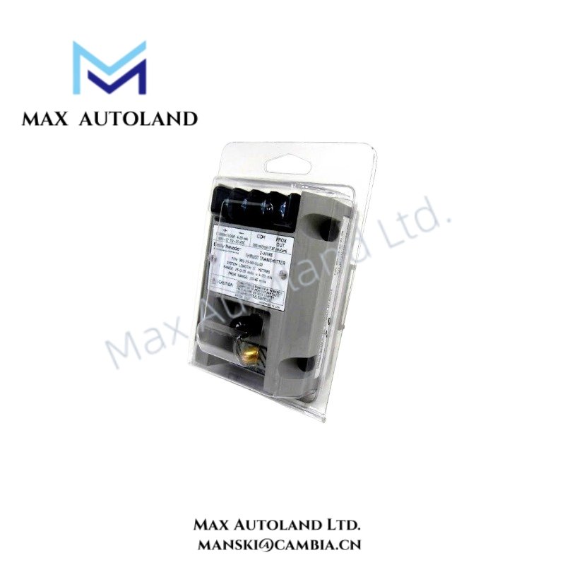
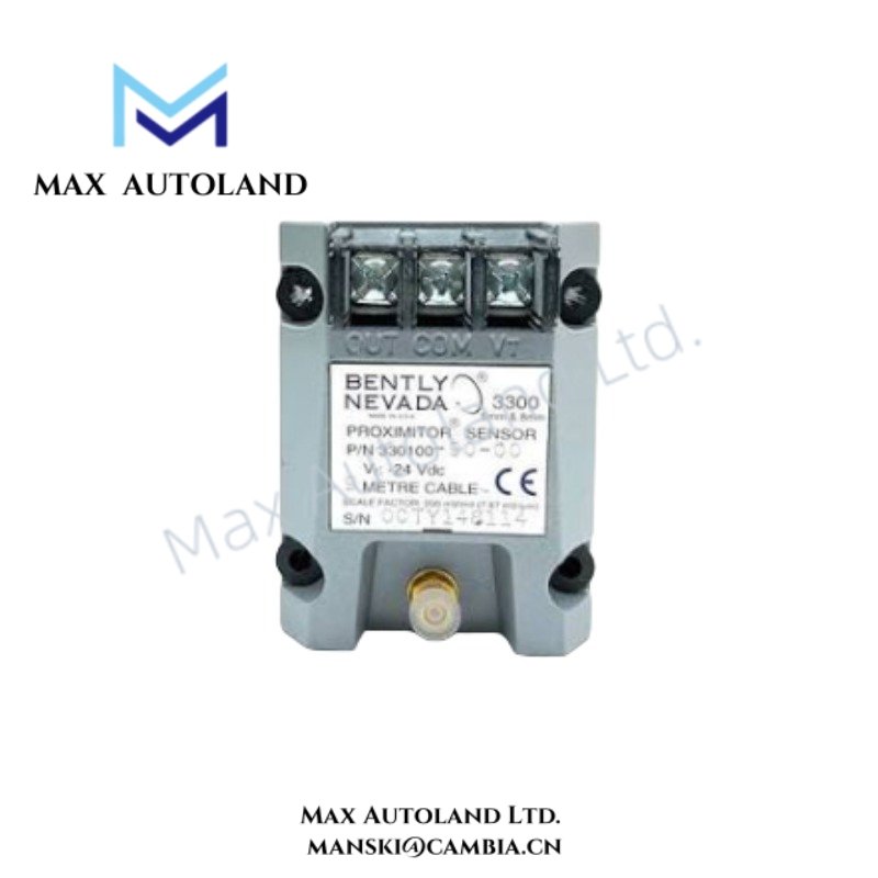
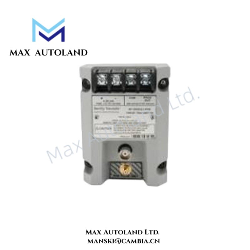
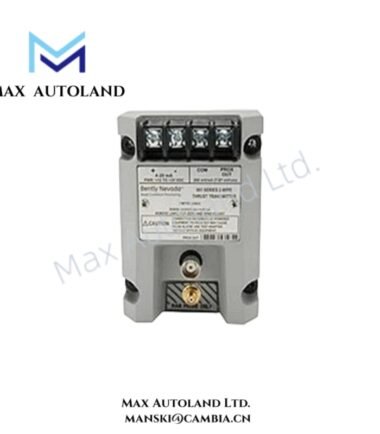
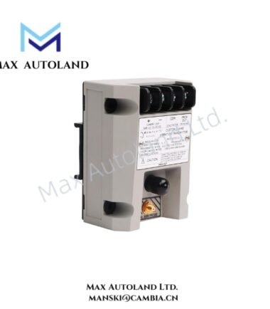
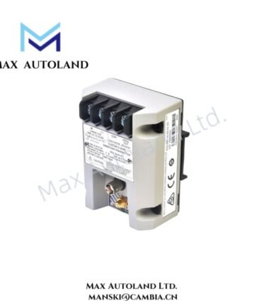
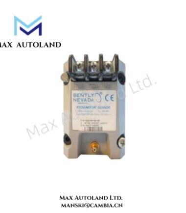
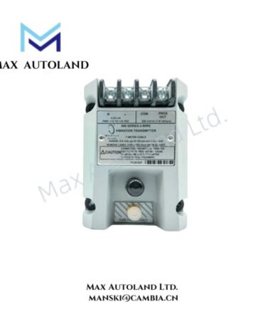
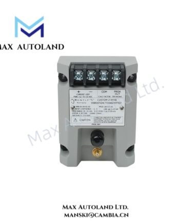
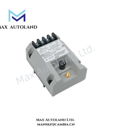
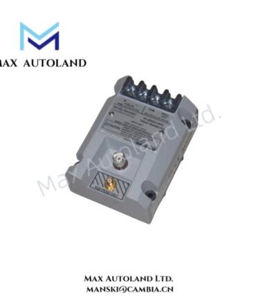
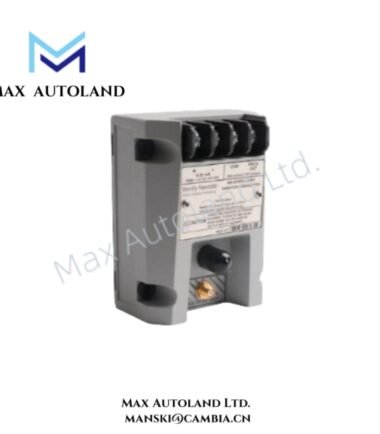
Configured for axial shaft position measurement in a machinery monitoring loop, the Bently Nevada 991-25-50-01-00 (991 Thrust Transmitter) conditions one 3300 NSv proximity probe signal and produces a proportional 4-20 mA output for DCS, PLC, or protection-system input circuits.
Hardware Specifications
| Parameter | Specification |
|---|---|
| Model | 991-25-50-01-00 |
| Brand | Bently Nevada |
| Product Type | Thrust (Axial Position) Transmitter |
| Origin | USA |
| Input Signal | 1 x 3300 NSv proximity probe with matching extension cable |
| Output Signal | 4-20 mA DC proportional to axial position |
| Circuit Type | 2-wire, loop-powered |
| Supply Voltage | +12 to +35 VDC at transmitter terminals |
| Full-Scale Range | 25-0-25 mils |
| System Length | 5.0 m (16.4 ft) total system length |
| Loop Accuracy | Within +/- 1.5% over specified full-scale range, typical |
| Maximum Loop Resistance | 1,000 ohm at 35 VDC, including cable resistance |
| Mounting | 35 mm DIN-rail clips |
| Approvals | Standard non-hazardous area configuration |
| Operating Temp | -35 deg C to +85 deg C |
| Storage Temp | -51 deg C to +100 deg C |
| Weight | Approx. 0.43 kg (0.9 lbm) |
| Power Consumption | Loop-powered; exact consumption not specified in the supplied data |
Eddy-Current Probe Scaling and Signal Conditioning
The 991 transmitter integrates proximity signal conditioning for a 3300 NSv probe and matching extension cable. It converts the probe response into a 4-20 mA signal proportional to axial shaft position.
The -25 range designation specifies a 25-0-25 mil measurement range. Therefore, installation personnel should verify the mechanical probe target position and electrical gap before commissioning the monitoring loop.
The transmitter also provides a test input for loop verification. In addition, the Not OK / Signal Defeat circuit drives the output below 3.6 mA within 100 microseconds when the probe circuit develops a fault condition.
Frequently Asked Questions (FAQ)
Q: What probe does the 991-25-50-01-00 accept?
A: It accepts one 3300 NSv non-contacting proximity probe with the specified matching extension cable.
Q: What electrical output does the transmitter provide?
A: The transmitter provides a 4-20 mA DC output proportional to the configured axial position range.
Q: Can the transmitter operate from a separate AC supply?
A: No. The supplied specifications define a 2-wire, loop-powered configuration requiring +12 to +35 VDC at the transmitter terminals.
Field Installation Guidelines
- Mount the transmitter using the specified 35 mm DIN-rail clips and maintain mechanical stability.
- Connect the 3300 NSv probe and matching extension cable according to the applicable wiring documentation.
- Route the probe signal wiring separately from high-current motor, switching, and power conductors where practical.
- Use appropriate cable shielding and terminate the shield according to the plant grounding architecture.
- Verify loop polarity before applying power to the transmitter.
- Confirm the probe gap and axial mechanical reference position before evaluating the 4-20 mA output.
- Check the loop resistance against the available supply voltage before commissioning.
- Use the test input only with a controlled DC test source suitable for the transmitter input circuit.
- Verify the Not OK output behavior during controlled maintenance testing before placing the monitoring channel into service.


Reviews
There are no reviews yet.