
Overview
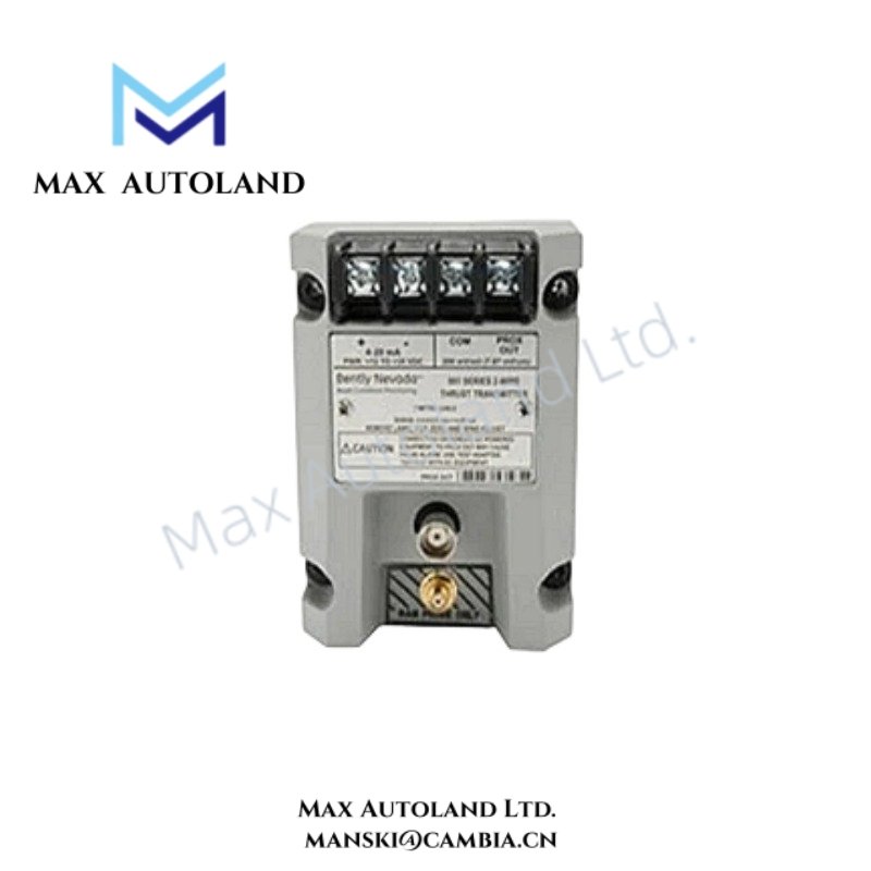
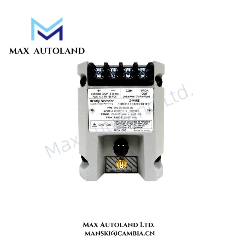
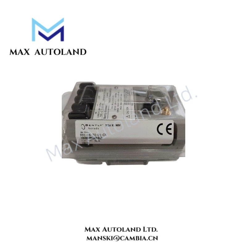
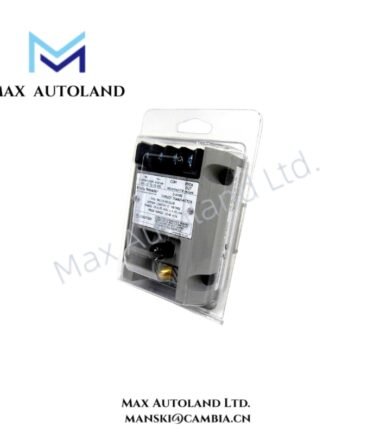
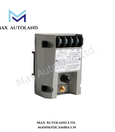
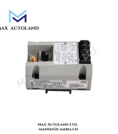
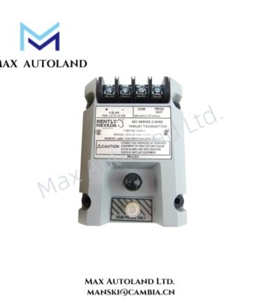
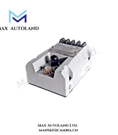
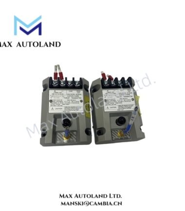
Configured for axial shaft position measurement in a thrust-bearing monitoring circuit, the Bently Nevada 991-06-70-01-CN (991 Thrust Transmitter) provides direct signal conditioning between the thrust-position sensing element and the connected monitoring loop. The unit uses a 0.6-0-0.6 mm full-scale range and accepts +12 to +35 VDC at the transmitter terminals.
Hardware Specifications
| Parameter | Specification |
|---|---|
| Model | 991-06-70-01-CN |
| Base Model | 991 |
| Product Type | Thrust Transmitter |
| Brand | Bently Nevada |
| Manufacturer | Bently Nevada |
| Origin | USA |
| Shipment Location | Xiamen, China |
| Weight | 0.44 kg |
| Estimated Shipping Dimensions | 7.3 x 6 x 10 cm |
| Full-scale Option | 0.6-0-0.6 mm |
| System Length Option | 7.0 meters (23.0 feet) |
| Mounting | 35 mm DIN-rail clips |
| Current Limiting | 23 mA typical |
| Agency Approval | CSA Division 2, ATEX Zone 0, ATEX Zone 2, ABS maritime approval |
Eddy-Current Probe Scaling and Axial Position Measurement
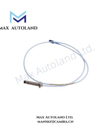
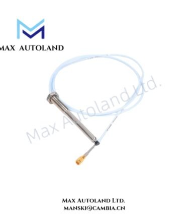
The 991 transmitter processes the signal associated with an axial-position sensing circuit and scales the measurement according to the selected 0.6-0-0.6 mm full-scale option. The 7.0 meter (23.0 feet) system-length option defines the specified probe and transmitter system configuration.
The transmitter requires +12 to +35 VDC at its terminals. Its typical current-limiting value is 23 mA, which provides a defined electrical limit within the connected loop. During installation, technicians should verify the sensor configuration, wiring continuity, supply polarity, and signal reference before applying operating power.
The 35 mm DIN-rail clip configuration provides mechanical attachment to a compatible DIN rail. Technicians should maintain physical separation between low-level measurement wiring and high-current or high-voltage conductors to reduce induced electrical interference.
Frequently Asked Questions (FAQ)
Q: What full-scale measurement option does the 991-06-70-01-CN use?
A: This configuration uses a 0.6-0-0.6 mm full-scale option.
Q: What supply voltage does the transmitter require?
A: The supplied specification requires +12 to +35 VDC at the transmitter terminal.
Q: What mounting arrangement does this model use?
A: The model uses 35 mm DIN-rail clips for mechanical installation.
Field Installation Guidelines
- Install the transmitter on a mechanically secure 35 mm DIN rail and verify that the clips engage correctly.
- Confirm the transmitter terminal wiring against the approved system drawing before energizing the circuit.
- Apply only the specified +12 to +35 VDC input range at the transmitter terminals.
- Route thrust-position signal wiring separately from high-voltage, motor, relay, and high-current cables where practical.
- Maintain proper cable shielding and terminate the shield according to the plant grounding design. Avoid creating unintended ground loops.
- Verify the 7.0 meter (23.0 feet) system-length configuration against the installed sensing system before commissioning.
- For installations involving CSA Division 2 or ATEX Zone 0 / Zone 2 requirements, verify that the complete installation satisfies the applicable hazardous-area certification and wiring requirements.
- After wiring, check terminal tightness, polarity, continuity, and sensor-loop integrity before placing the thrust monitoring circuit into service.

Reviews
There are no reviews yet.