
Overview
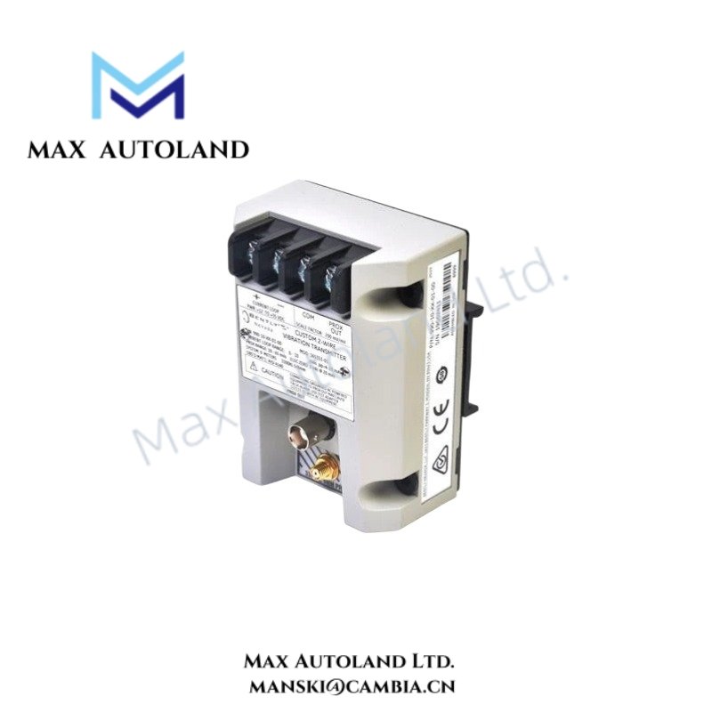
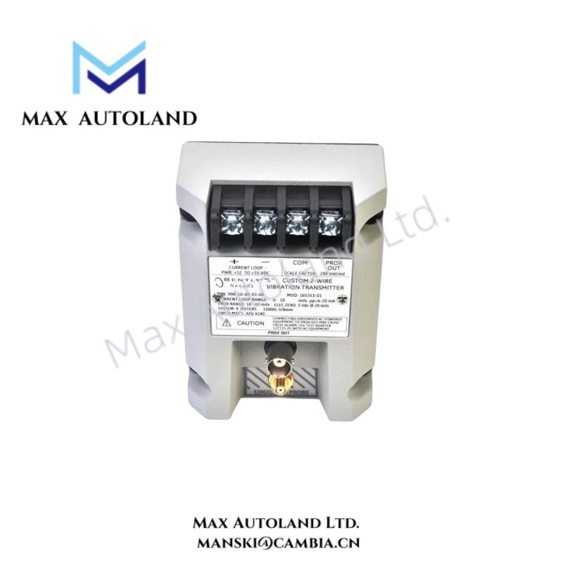
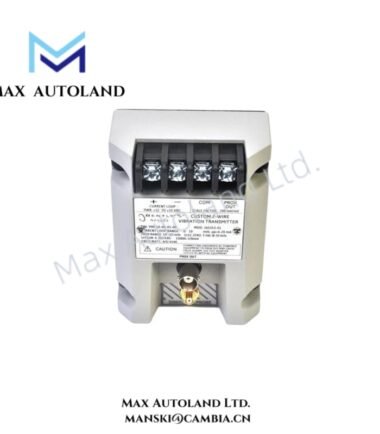
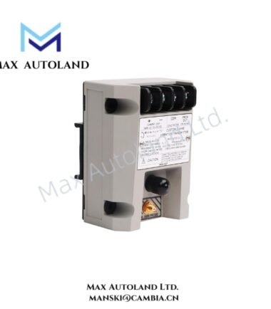
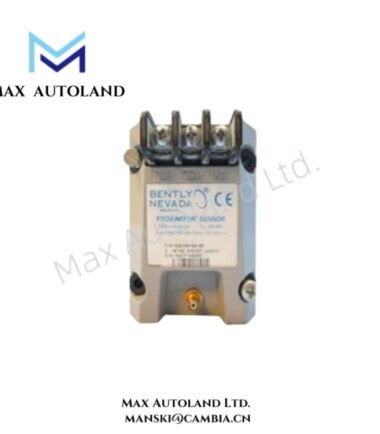
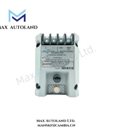
The Bently Nevada 991-01-XX-01-00 MOD: 284318-01, also cataloged as the 991 Thrust Transmitter, converts axial shaft position from a 3300 NSv proximity probe into a loop-current signal for machinery monitoring.
Hardware Specifications
| Parameter | Specification |
|---|---|
| Model | 991-01-XX-01-00 MOD: 284318-01 |
| Base Model | 991 |
| Product Type | Thrust Transmitter |
| Brand | Bently Nevada |
| Manufacturer | Bently Nevada |
| Origin | USA |
| Shipment Location | Xiamen, China |
| Weight | 0.5 kg |
| Dimensions | 10 x 7.4 x 5.8 cm estimated shipping size |
| Power Consumption | Loop-powered; requires +12 to +35 VDC at transmitter terminal |
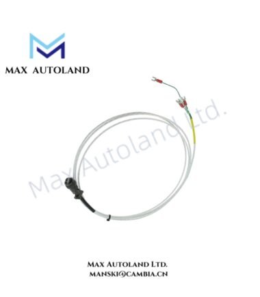
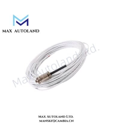
| Input | 1 non-contacting 3300 NSv proximity probe and extension cable |
| Output | 4-20 mA thrust position signal |
| Current Limiting | 23 mA typical |
| System Length Option | 5.0 m or 7.0 m |
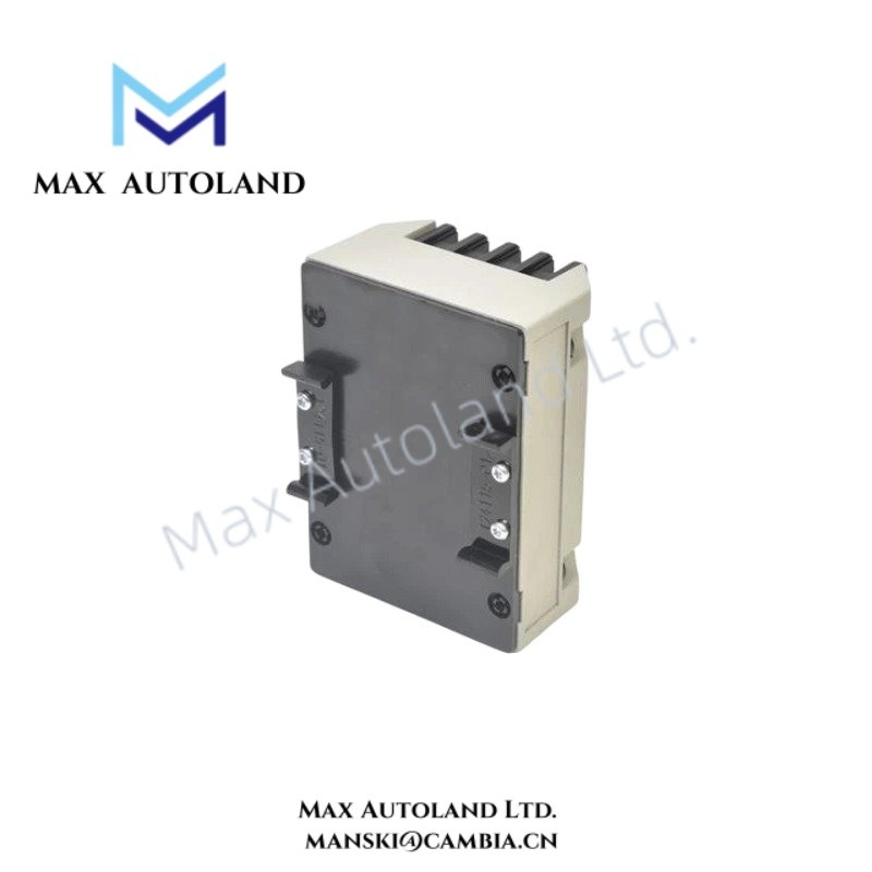
| Mounting | 35 mm DIN-rail clips |
Eddy-Current Probe Scaling and Axial Position
The 991 transmitter accepts the signal from one 3300 NSv non-contacting proximity probe and its matching extension cable. The probe detects shaft axial displacement through the eddy-current measurement principle. The transmitter conditions the probe signal and produces a proportional 4-20 mA output for monitoring equipment.
The specified system length options are 5.0 m and 7.0 m. The selected probe and extension cable combination must match the transmitter configuration. Proper probe installation also requires stable mechanical positioning relative to the monitored shaft surface.
The transmitter requires +12 to +35 VDC at its terminal. It limits loop current to approximately 23 mA under the specified current-limiting condition.
Frequently Asked Questions (FAQ)
Q: What probe does the 991-01-XX-01-00 MOD: 284318-01 accept?
A: It accepts one non-contacting 3300 NSv proximity probe with its corresponding extension cable.
Q: What power supply does the transmitter require?
A: The transmitter requires +12 to +35 VDC at the transmitter terminal.
Q: How should the transmitter be mounted?
A: The specified mounting option uses 35 mm DIN-rail clips. Install the transmitter on a mechanically stable DIN rail and maintain accessible wiring connections.
Field Installation Guidelines
- Install the transmitter on a suitable 35 mm DIN rail and secure the clips before connecting field wiring.
- Route the proximity probe cable separately from high-current power conductors and switching circuits where practical.
- Maintain the specified probe and extension cable combination for the selected 5.0 m or 7.0 m system length.
- Connect the required +12 to +35 VDC supply directly to the transmitter terminals with correct polarity.
- Verify the 4-20 mA signal loop wiring before applying power.
- Use appropriate cable shielding and terminate shields according to the plant grounding practice. Avoid creating unintended ground loops.
- Confirm stable mechanical probe mounting and maintain the required probe-to-target relationship during commissioning.
- Verify transmitter output response against the expected shaft axial-position condition before placing the machinery monitoring loop into service.




Reviews
There are no reviews yet.