



Overview
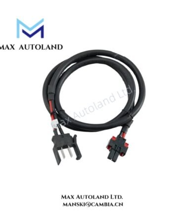
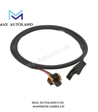
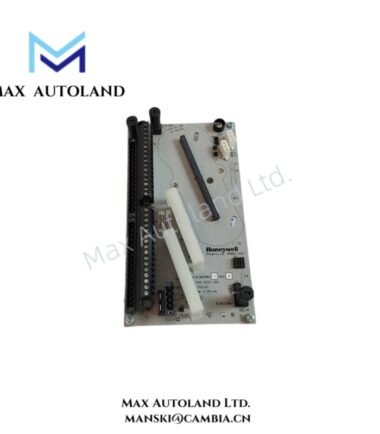
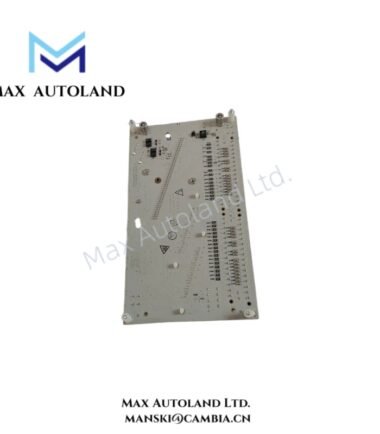
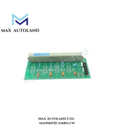
Configured for 24 VDC power distribution in Honeywell Safety Manager systems, the Honeywell FS-PDC-FTA24P (PDC-FTA24P Power Distribution Cable) provides a direct electrical path between the FC-PDB-0824P Power Distribution Board and field termination assemblies or other 24 VDC devices.
Hardware Specifications
| Parameter | Specification |
|---|---|
| Model | FS-PDC-FTA24P |
| Base Model | PDC-FTA24P |
| Brand | Honeywell |
| Product Type | Power Distribution Cable |
| Application | 24 VDC power distribution |
| Compatible Board | FC-PDB-0824P |
| Voltage | 24 VDC +/-20% |
| Current Rating | 2 A continuous |
| Conductor | 2 x 1.31 mm2 (AWG 16) |
| Isolation | 300 V RMS, 90 deg C |
| Operating Temp | -20 to +70 deg C |
| Power Consumption | Not specified; passive cable |
| Weight | 0.1 kg |
| Dimensions | 17 x 13 x 2 cm estimated shipping size |
24 VDC Power Distribution Characteristics
The FS-PDC-FTA24P carries 24 VDC from the FC-PDB-0824P Power Distribution Board toward connected field termination assemblies and other 24 VDC loads. Its two-conductor construction uses 1.31 mm2 (AWG 16) conductors and supports a continuous current rating of 2 A.
The specified supply range is 24 VDC +/-20%. Therefore, the connected circuit should remain within the stated voltage range during normal operation. The cable provides 300 V RMS isolation at 90 deg C according to the supplied specification.
Frequently Asked Questions
Q: What power distribution board does the FS-PDC-FTA24P connect to?
A: The supplied data identifies the FC-PDB-0824P as the associated Power Distribution Board.
Q: What voltage and continuous current does the FS-PDC-FTA24P support?
A: It supports 24 VDC +/-20% and a 2 A continuous current rating.
Q: What conductor size does the FS-PDC-FTA24P use?
A: The cable uses two 1.31 mm2 (AWG 16) conductors.
Field Installation Guidelines
- Verify the FS-PDC-FTA24P model before installation and confirm compatibility with the FC-PDB-0824P connection point.
- Confirm that the connected circuit operates within the specified 24 VDC +/-20% supply range.
- Keep the continuous load within the 2 A current rating.
- Route the cable securely inside the control cabinet and prevent excessive bending or mechanical stress at the connection points.
- Separate power wiring from signal and communication wiring where the cabinet layout permits.
- Check conductor terminations for secure mechanical contact before energizing the circuit.
- Inspect the cable insulation and connectors for damage before installation.
- De-energize the relevant power circuit before making or changing cable connections.



Reviews
There are no reviews yet.