

Overview
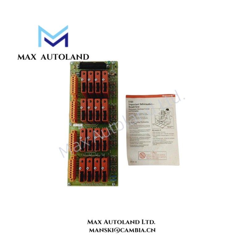
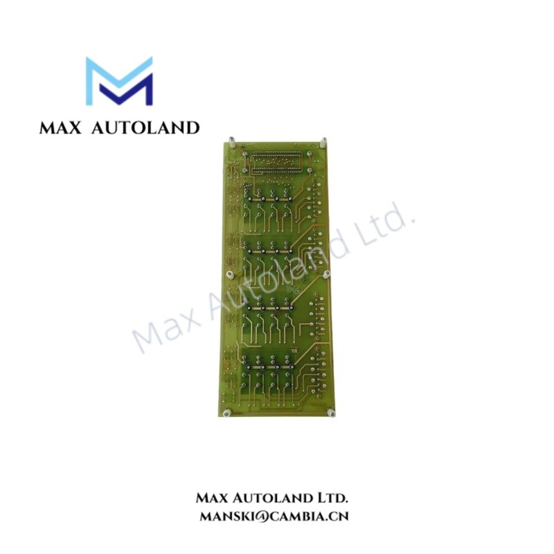
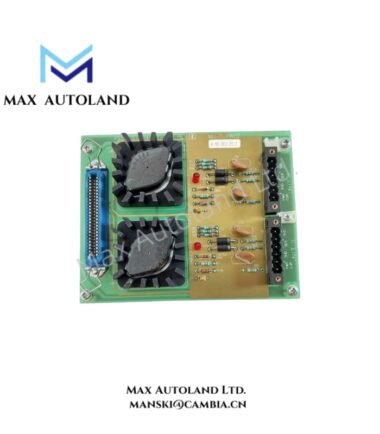
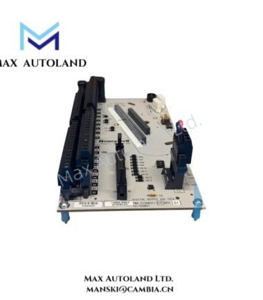
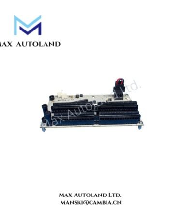
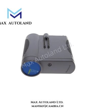
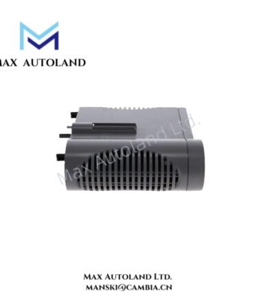
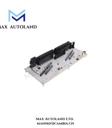
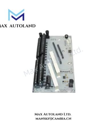
The Honeywell 51304650-100, also cataloged as the MU-TD0D13 Digital Output Module, provides field-level discrete output interfacing within Honeywell TDC 3000 and Experion PKS control architectures. It transfers output commands from the control system to connected discrete field circuits.
Hardware Specifications
| Parameter | Specification |
|---|---|
| Model | MU-TD0D13 |
| Part Number | 51304650-100 |
| Brand | Honeywell |
| Module Type | Digital Output / Discrete Output Module |
| Application | Industrial Process Control / DCS |
| System Compatibility | Honeywell TDC 3000 / Experion PKS environments, subject to system revision |
| Network Architecture | Universal Control Network (UCN) and associated Honeywell control architectures |
| Signal Type | Discrete / Digital Output |
Honeywell DCS Signal Interface Characteristics
The MU-TD0D13 operates as a discrete output interface between the Honeywell control system and field-side output circuits. The module receives output commands through the system I/O architecture and applies the corresponding discrete state to its output circuitry.
For process instrumentation architectures that use analog 4-20 mA HART loops, this module should not be treated as an analog loop interface. Its stated function is discrete output handling. Therefore, channel wiring and field device selection must match the output circuit type specified for the applicable Honeywell I/O subsystem.
Channel-to-channel isolation, output voltage limits, current capacity, and field termination details are revision-dependent parameters and are not specified in the supplied data. Verify these values against the applicable Honeywell hardware documentation before installation.
Frequently Asked Questions (FAQ)
Q: What signal type does the MU-TD0D13 handle?
A: The supplied information identifies the MU-TD0D13 as a Digital Output / Discrete Output Module. Exact output electrical ratings are not provided.
Q: Can the 51304650-100 be installed in any Honeywell TDC 3000 or Experion PKS system?
A: Compatibility depends on the system revision, I/O architecture, firmware, carrier arrangement, and associated termination hardware. Verify the complete hardware configuration before installation.
Q: Are the output voltage and current ratings specified for this module?
A: No. The supplied data does not define output voltage, current limits, channel count, or detailed wiring characteristics. Use the applicable Honeywell hardware manual for these parameters.
Field Installation Guidelines
- Confirm the complete part number and module identification before installation.
- Verify that the chassis, carrier, I/O subsystem, and system revision support MU-TD0D13.
- Isolate field power before connecting or disconnecting field wiring.
- Install the module according to the specified rack or carrier orientation.
- Route discrete signal wiring separately from high-voltage power conductors where practical.
- Maintain appropriate segregation between low-level control wiring and high-energy switching circuits.
- Terminate cable shields according to the plant grounding and Honeywell system wiring requirements.
- Verify field polarity and common connections against the applicable termination assembly drawing.
- Confirm output load compatibility before energizing the connected field circuit.
- Perform point-to-point continuity checks before applying field power.
- After installation, verify each configured output state from the control system and confirm the corresponding field device response.
- Do not infer undocumented voltage, current, channel, or isolation ratings from the part number alone.
Reviews
There are no reviews yet.