

Overview
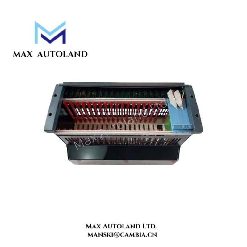
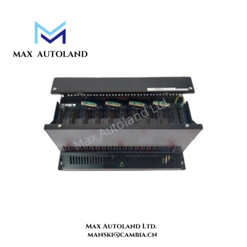
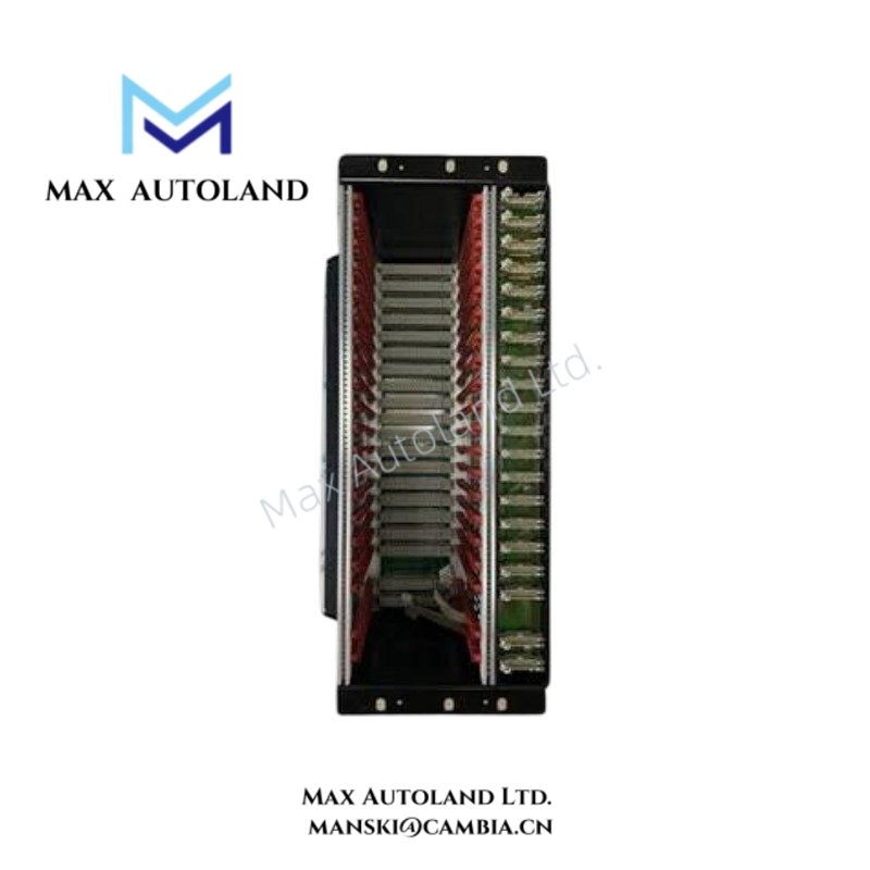
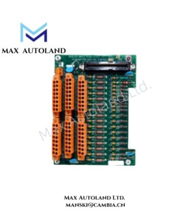
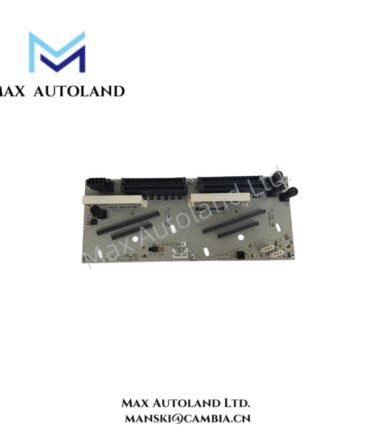
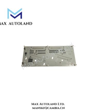
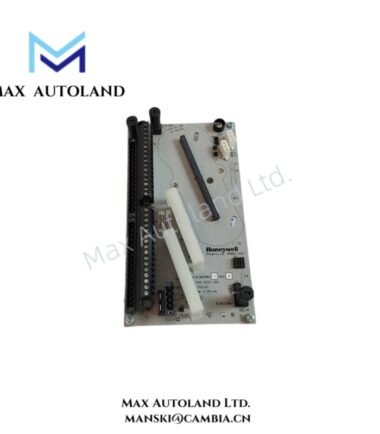
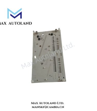
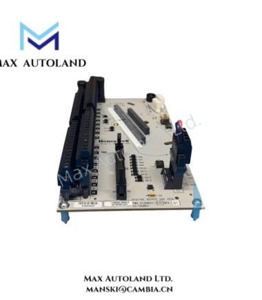
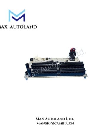
Configured for redundant I/O module installation, the Honeywell FS-IOCHAS-0001R (IOCHAS-0001R I/O Chassis) provides the physical chassis structure and power distribution interface for up to 9 pairs of redundant I/O modules. The chassis uses separate 5 V power feeds for the IO-0001 slots and accepts a 24 V DC input supply.
Hardware Specifications
| Parameter | Specification |
|---|---|
| Model | FS-IOCHAS-0001R |
| Base Model | IOCHAS-0001R |
| Brand | Honeywell |
| Product Type | I/O Chassis for Redundant Module |
| Origin | USA |
| Weight | 7.6 kg |
| Dimensions | 48.2 x 30 x 22 cm shipping size |
| Operating Temp | -40 deg C to +70 deg C |
| Storage Temp | -50 deg C to +85 deg C |
| Humidity | 5-95% RH, condensing |
| Vibration | 5 g @ 10-500 Hz, IEC 60068-2-6 |
| Input Voltage | 24 V DC, 18-36 V DC |
| 5V-1 Current | 35 mA, IO-0001 slot 20 |
| 5V-2 Current | 35 mA, IO-0001 slot 21 |
| Redundant I/O Capacity | Up to 9 pairs of redundant I/O modules |
| Approvals | CE, UL, CSA, TUV, FM |
Honeywell DCS Redundant I/O Chassis Architecture
The FS-IOCHAS-0001R provides the mechanical mounting and electrical distribution structure for redundant I/O module pairs. The chassis supports up to 9 redundant pairs, while the specified IO-0001 positions receive dedicated 5 V feeds.
The available power data identifies 35 mA for the 5V-1 feed at IO-0001 slot 20 and 35 mA for the 5V-2 feed at IO-0001 slot 21. These values describe the stated chassis-side current allocation and should not be interpreted as the total current consumption of every installed I/O module.
The chassis accepts a nominal 24 V DC input within the specified 18-36 V DC range. Therefore, installation should maintain the DC supply within this range at the chassis input terminals.
Frequently Asked Questions
Q: How many redundant I/O module pairs can the FS-IOCHAS-0001R accommodate?
A: The specified chassis supports up to 9 pairs of redundant I/O modules.
Q: What are the specified 5 V power-feed currents?
A: The 5V-1 feed for IO-0001 slot 20 is specified at 35 mA. The 5V-2 feed for IO-0001 slot 21 is also specified at 35 mA.
Q: What DC input range does the chassis accept?
A: The chassis uses a 24 V DC nominal input and specifies an operating input range of 18-36 V DC.
Field Installation Guidelines
- Mount the chassis on a mechanically stable surface that supports the stated equipment weight and maintains clearance around wiring and module access areas.
- Connect the DC supply with correct polarity and verify that the supply remains within the specified 18-36 V DC input range.
- Route power wiring separately from high-energy switching circuits and high-frequency sources where practical.
- Secure all chassis and module connections before energizing the system.
- Keep signal and power conductors properly separated to reduce electrical interference.
- Terminate cable shields according to the system grounding design and site electrical standards.
- Verify the redundant I/O module positions against the approved system configuration before inserting modules.
- Confirm the 5V-1 and 5V-2 connections before applying power, particularly for IO-0001 slot 20 and slot 21.
- Check the installed chassis and module assembly for mechanical damage, loose connections, and incorrect wiring before commissioning.

Reviews
There are no reviews yet.