
Overview
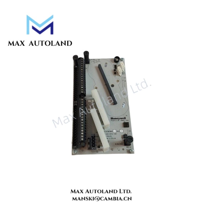
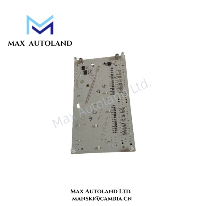
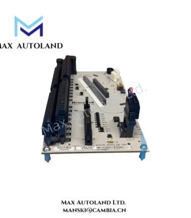
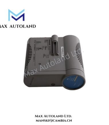
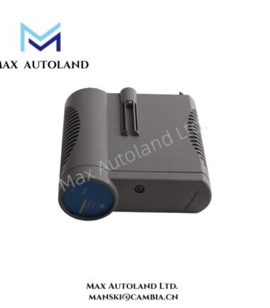
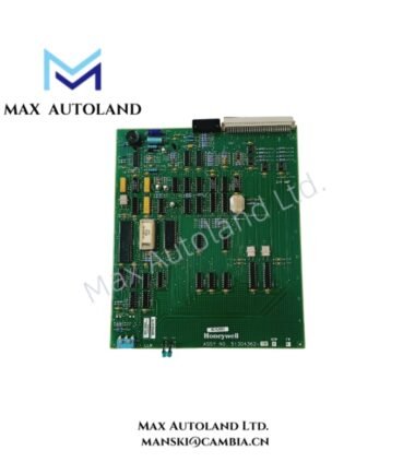
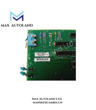
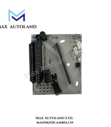
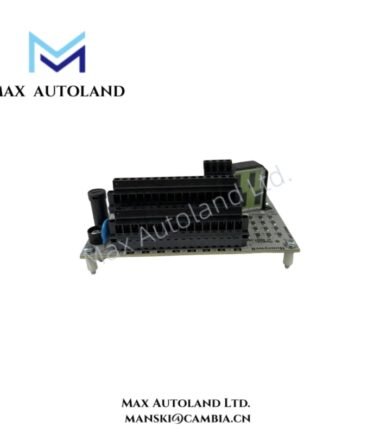
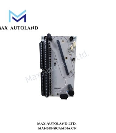
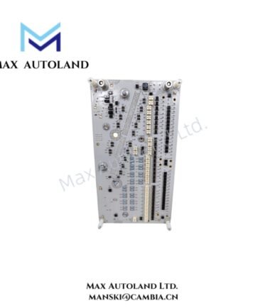
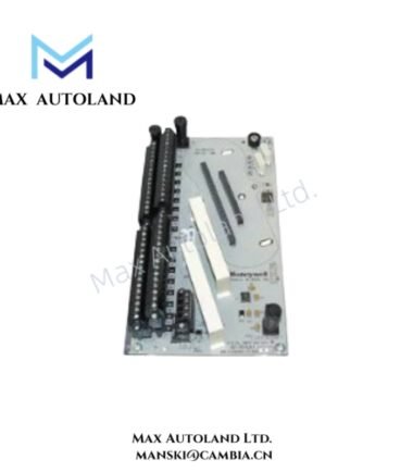
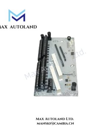
Configured for 32-channel discrete signal acquisition in Honeywell control systems, the Honeywell CC-TDIL51 51307083-175 (51307083-175 Digital Input Module) provides isolated electrical input sensing for field digital signals.
Hardware Specifications
| Parameter | Specification |
|---|---|
| Model | CC-TDIL51 51307083-175 |
| Spare Model | 51307083-175 |
| Brand | Honeywell |
| Product Type | Digital Input Module |
| Input Channels | 32 |
| Origin | USA |
| Weight | 0.5 kg |
| Dimensions | 26 x 115.2 x 7.5 cm estimated shipping size |
| Galvanic Isolation | 1000 VAC RMS |
| Isolation Technique | Optical isolation in IOM |
| DI Power Voltage Range | 18 to 30 VDC |
| ON Sense Voltage | 13 VDC minimum |
| ON Sense Current | 3 mA minimum |
| OFF Sense Voltage | 5 VDC maximum |
| OFF Sense Current | 1.2 mA maximum |
| Input Impedance | 4.2 kOhm |
| Absolute Delay | 5 ms +/- 20% across input filter and isolation |
Honeywell Process Control and Channel Isolation
The CC-TDIL51 uses optical isolation within the I/O module to separate field input circuitry from internal module electronics. The specified 1000 VAC RMS galvanic isolation limits direct electrical coupling between the input side and isolated circuitry.
Furthermore, each digital input accepts an 18 to 30 VDC DI power range. The input circuit identifies an ON state at a minimum of 13 VDC or 3 mA, while an OFF state requires a maximum of 5 VDC or 1.2 mA. The 4.2 kOhm input impedance defines the electrical load presented to the connected field circuit.
The input filter and isolation path introduce an absolute delay of 5 ms +/- 20%. Therefore, control logic and sequence applications should account for this hardware response time when evaluating fast discrete transitions.
Frequently Asked Questions (FAQ)
Q: How many digital input channels does the CC-TDIL51 provide?
A: The module provides 32 digital input channels.
Q: What isolation does the CC-TDIL51 provide?
A: The supplied specifications state 1000 VAC RMS galvanic isolation using optical isolation within the I/O module.
Q: What is the specified input response delay?
A: The absolute delay across the input filter and isolation is 5 ms +/- 20%.
Field Installation Guidelines
- Verify the module model and wiring assignment before connecting field circuits.
- Confirm that the applied DI supply voltage remains within the specified 18 to 30 VDC range.
- Verify ON and OFF sensing levels against the connected field device output characteristics.
- Route digital input wiring separately from high-current switching conductors where practical.
- Maintain appropriate separation from high-voltage and high-frequency sources to reduce induced electrical noise.
- Connect cable shields according to the system grounding design and avoid creating unintended ground loops.
- Check terminal polarity and field circuit continuity before energizing the module.
- Do not infer unsupported operating temperature, power consumption, or hot-swap characteristics from the supplied specifications.
Reviews
There are no reviews yet.