

Overview
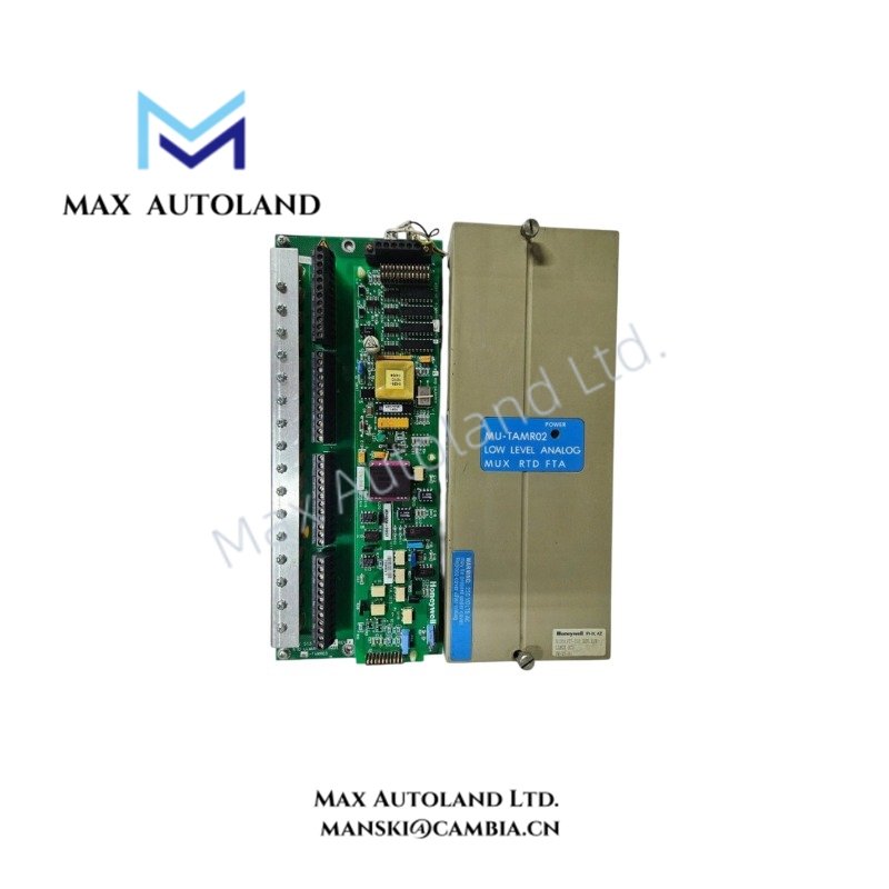
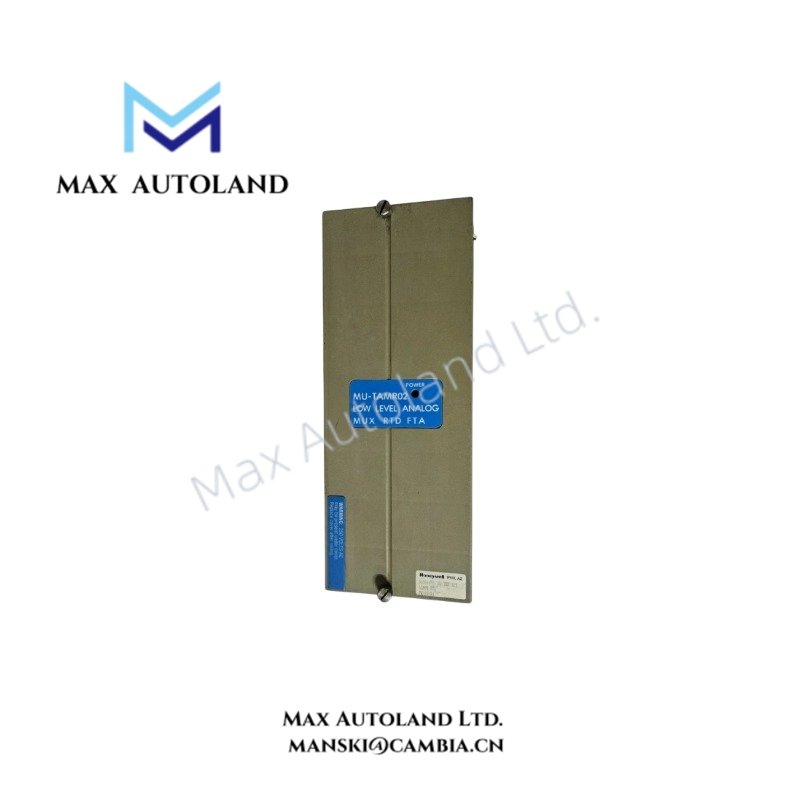
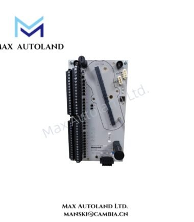
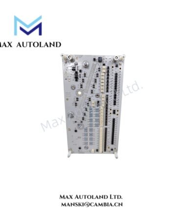
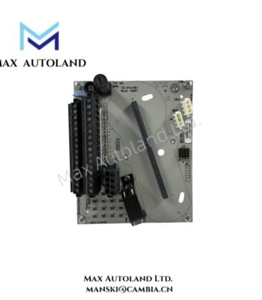
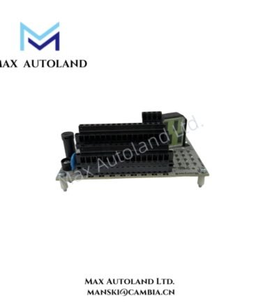
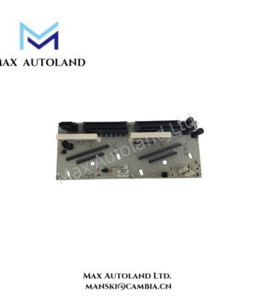
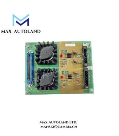
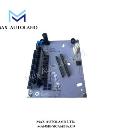
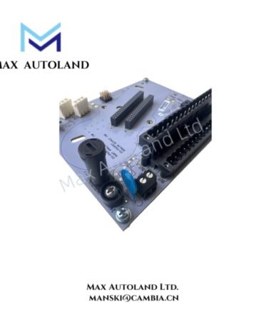
The Honeywell 51304477-100, also cataloged as the MU-TAMR02 Low-Level Analog Input Multiplexer RTD Field Termination Assembly, provides physical termination and multiplexing for 16 low-level RTD input channels within Honeywell TDC 3000 and Experion PKS Process Manager architectures. The assembly routes field RTD signals toward the associated input processing hardware.
Hardware Specifications
| Parameter | Specification |
|---|---|
| Model | MU-TAMR02 |
| Part Number | 51304477-100 |
| Brand | Honeywell |
| Product Type | Low-Level Analog Input Multiplexer RTD Field Termination Assembly |
| System Compatibility | Honeywell TDC 3000 / Experion PKS Process Manager architecture |
| Input Channels | 16 low-level analog / RTD channels |
| Signal Type | RTD temperature signals |
| Terminal Type | Compression terminal blocks |
| Calibration | Dedicated RTD calibration circuitry on removable daughter board |
| Mounting Size | Size B |
| Approximate Length | 307 mm |
| Dimensions | Size B; approximately 307 mm length; complete dimensions not specified |
| Field Wiring | Direct termination through compression terminal blocks |
| Primary Function | RTD signal termination and multiplexing |
RTD Signal Termination and Calibration
The MU-TAMR02 terminates low-level RTD signals at the field interface before routing them to the associated Honeywell input processing hardware. Therefore, field wiring remains concentrated at the FTA rather than directly at the I/O processor.
The assembly provides 16 RTD input channels. In addition, its removable daughter board contains dedicated RTD calibration circuitry. Technicians can therefore service or calibrate the associated circuitry without disconnecting the field wiring from the main termination assembly.
Because RTD signals operate at low signal levels, installation should maintain physical separation from high-voltage conductors and other sources of electrical interference. Where shielded RTD wiring is specified by the system design, the shield termination method should follow the Honeywell installation documentation for the specific controller and I/O architecture.
Frequently Asked Questions
Q: How many RTD input channels does the MU-TAMR02 provide?
A: The supplied specification identifies 16 low-level analog / RTD input channels.
Q: Can the RTD calibration circuitry be removed without disconnecting the field wiring?
A: Yes. The supplied data specifies a removable daughter board containing the RTD calibration circuitry, allowing calibration or replacement without disconnecting field wiring from the main board.
Q: What type of field termination does the assembly use?
A: The MU-TAMR02 uses compression terminal blocks for field wiring termination.
Field Installation Guidelines
- Install the FTA in the designated Honeywell mounting location and maintain the required mechanical clearance for wiring access.
- Connect RTD field conductors to the designated compression terminals according to the applicable system wiring documentation.
- Route RTD wiring separately from high-voltage power cables and high-current switching conductors.
- Maintain consistent conductor identification throughout the field cable, FTA, and associated I/O channel.
- Apply the specified shield grounding method at the designated termination point. Avoid creating unintended shield ground loops.
- Verify terminal tightness and conductor seating before energizing or commissioning the input circuit.
- When servicing the removable calibration daughter board, follow the applicable Honeywell maintenance procedure and observe electrostatic discharge precautions.
- Confirm channel assignment and RTD sensor wiring against the control system configuration before placing the input channels into service.

Reviews
There are no reviews yet.