
Overview
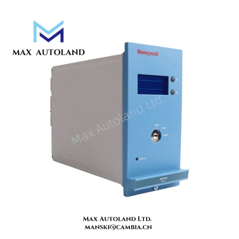
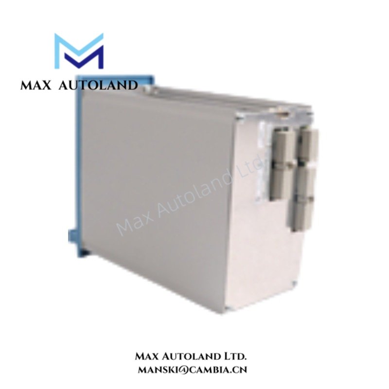
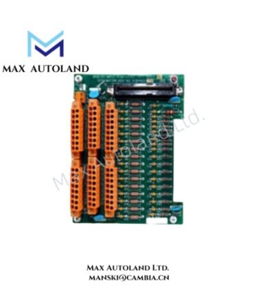
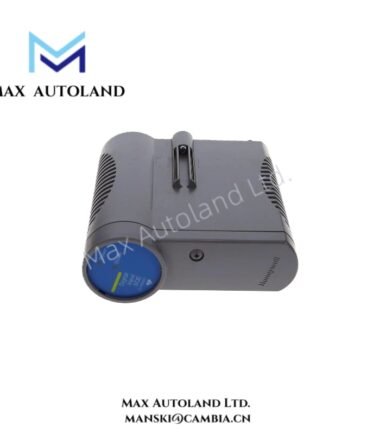
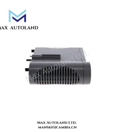
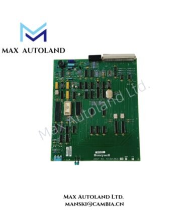
Configured for safety logic execution and processor-level data handling in the Honeywell Safety Manager system, the Honeywell FC-QPP-0002 (QPP-0002 Quad Processor Pack) provides the processing hardware for safety-critical control logic, field I/O data processing, and safety output execution.
Hardware Specifications
| Parameter | Specification |
|---|---|
| Model | FC-QPP-0002 |
| Base Model | QPP-0002 |
| Brand | Honeywell |
| Product Type | Quad Processor Pack / SIS Controller Module |
| System | Honeywell Safety Manager |
| Weight | Approximately 1.2-1.3 kg |
| Dimensions | Approximately 176 mm x 88.5 mm x 212 mm |
| Operating Temp | -5 deg C to +70 deg C |
| Storage Temp | -40 deg C to +85 deg C |
| Relative Humidity | 10% to 95%, non-condensing |
| 24 VDC Supply | 24 VDC, -15% to +30% |
| 24 VDC Current | Maximum 25 mA |
| 5 VDC Supply | 5 VDC, +/-5%, via backplane |
| 5 VDC Current | Maximum 1.2 A |
| Diagnostic Coverage | Greater than 99% |
| Safety Integrity Level | SIL 3, IEC 61508 |
| Redundant Architecture | 2oo4D in redundant configuration |
| Processor Structure | Dual-processor / dual-memory architecture |
| Hardware Diagnostics | Hardware data comparison and watchdog monitoring |
| Approvals | CE, UL, CSA, TUV, FM |
| Compatibility | Backward compatible with QPP-0001 with R121 firmware or higher |
Honeywell Safety Manager Processing Architecture
The FC-QPP-0002 processes safety logic and exchanges data with the Safety Manager I/O structure. Its dual-processor and dual-memory architecture performs hardware data comparisons during read and write operations. The internal watchdog monitors task execution and processor timing.
For redundant operation, two QPP modules form a 2oo4D voting architecture. The system can also operate with a single QPP module in a non-redundant configuration. The supplied specifications identify diagnostic coverage above 99% and SIL 3 certification according to IEC 61508.
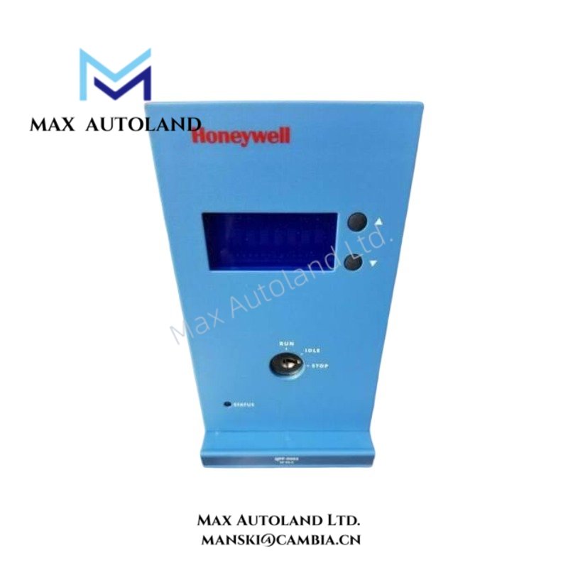
The front interface provides diagnostic and operating information, including diagnostic codes, forced-point count, communication settings, battery voltage, 5 VDC rail voltage, internal temperature, date/time, and firmware revision.
Frequently Asked Questions
Q: What backplane current does the FC-QPP-0002 require?
A: The module requires a maximum of 1.2 A from the 5 VDC backplane supply. It also requires 24 VDC at a maximum current of 25 mA.
Q: Can the FC-QPP-0002 operate in a redundant configuration?
A: Yes. Two QPP modules can form a redundant 2oo4D voting architecture. A single module supports non-redundant operation.
Q: Is the FC-QPP-0002 compatible with QPP-0001?
A: Yes. The supplied data specifies backward compatibility with QPP-0001 when R121 firmware or higher is installed.
Field Installation Guidelines
Install the FC-QPP-0002 in the specified Honeywell Safety Manager chassis position and secure the module according to the system hardware installation procedure.
Before installation, isolate power and verify that the chassis, backplane, and module connectors are free from contamination or mechanical damage. Align the module with the designated guide rails and apply even insertion force.
Maintain proper separation between power wiring and signal or communication wiring. Route shielded signal cables according to the Safety Manager installation requirements. Terminate cable shields according to the system grounding design and avoid creating unintended ground loops.
Verify the 5 VDC backplane supply and 24 VDC supply before commissioning. After installation, check the front-panel diagnostic information and confirm that the processor, memory, power rails, and communication interfaces report normal status.
For redundant configurations, follow the approved Safety Manager replacement and changeover procedure before removing or inserting a processor module. Do not treat hot-swap capability as an authorization to replace the module without applying the site’s safety isolation and maintenance procedure.
Reviews
There are no reviews yet.