
Overview
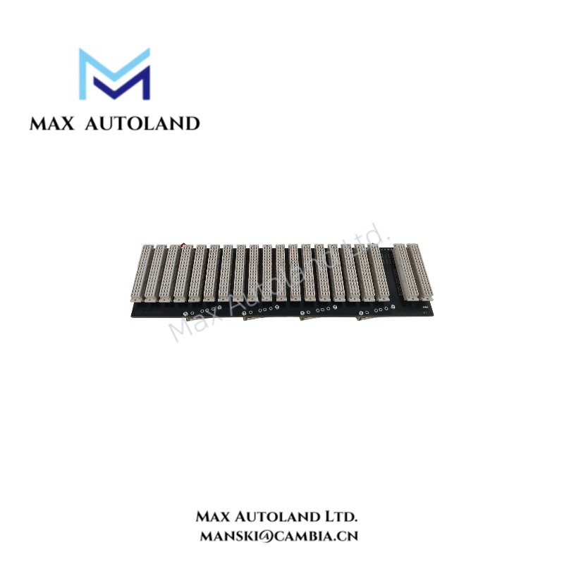
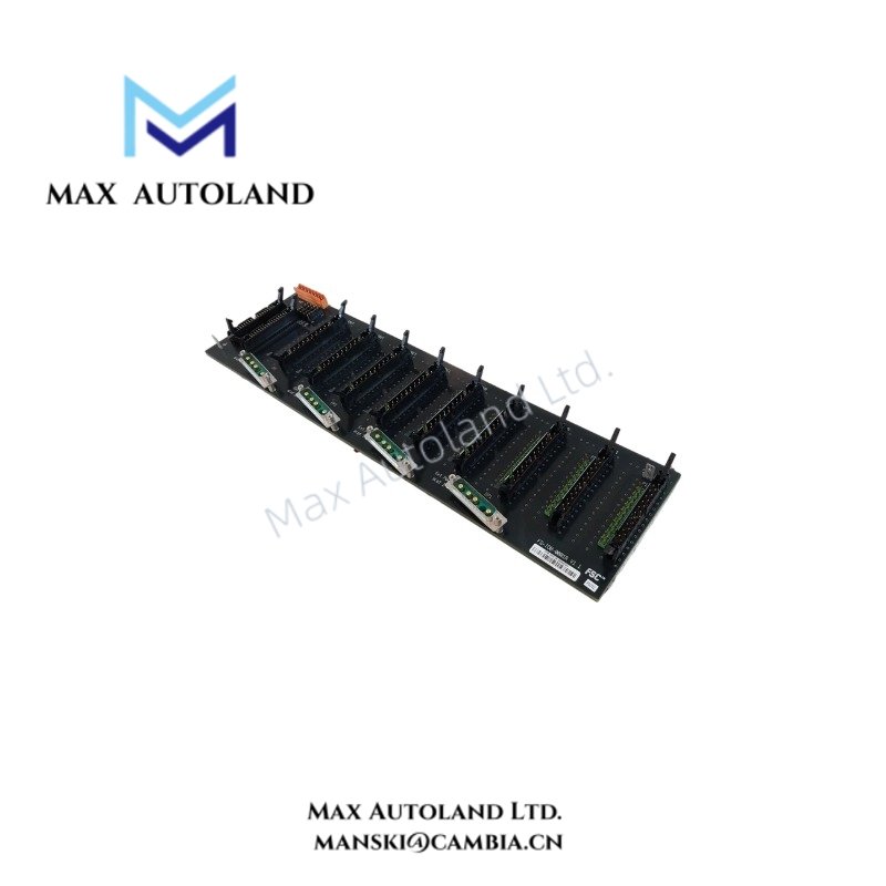
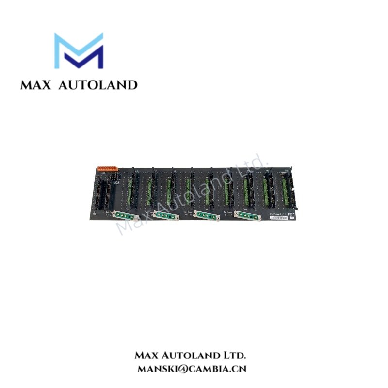
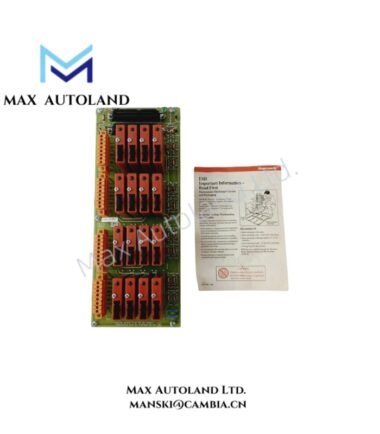
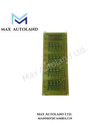
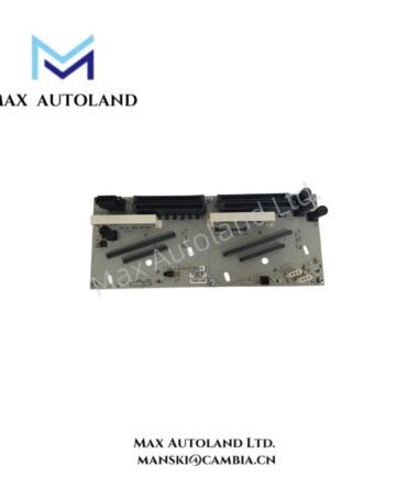
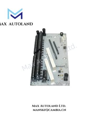
Configured for redundant I/O interconnection in a Honeywell safety control system, the Honeywell FS-IOB-0001R (FS-IOB-0001R Redundant I/O Backplane) provides the physical mounting and electrical interface for redundant I/O modules. It accepts dual 24 VDC input power and supports rack or DIN rail installation.
Hardware Specifications
| Parameter | Specification |
|---|---|
| Model | FS-IOB-0001R |
| Brand | Honeywell |
| Product Type | Redundant I/O Backplane |
| Origin | USA |
| Weight | 0.38 kg |
| Dimensions | Not specified; estimated shipping size: 48.3 x 29.5 x 23.5 cm |
| Mounting | 19 in rack or DIN rail |
| Input Voltage | Dual 24 VDC |
| Power Consumption | 30 W base; 400 W maximum load |
| Isolation | 1500 V AC |
| Surge Protection | +/- 4 kV |
| Operating Temp | -40 to +70 deg C |
| Storage Temp | -50 to +85 deg C |
| Humidity | 5-95% RH, non-condensing |
| Vibration | 5 g at 10-500 Hz |
Honeywell I/O Power and Isolation Characteristics
The FS-IOB-0001R uses dual 24 VDC inputs to supply its redundant I/O backplane arrangement. The supplied data specifies a 30 W base power requirement and a maximum load of 400 W.
The backplane provides 1500 V AC isolation. It also specifies +/- 4 kV surge protection. Therefore, installation should maintain appropriate separation between power wiring, I/O wiring, and other electrical circuits.
The available specifications do not identify a specific 4-20 mA HART interface, FOUNDATION Fieldbus interface, or Profibus PA interface for this backplane. Such protocol functions should therefore not be assigned to the FS-IOB-0001R without system documentation confirming them.
Frequently Asked Questions
Q: What input power does the FS-IOB-0001R require?
A: The backplane uses dual 24 VDC input power. The supplied data specifies 30 W base consumption and 400 W maximum load.
Q: Can the FS-IOB-0001R mount on a DIN rail?
A: Yes. The specified mounting options are a 19 in rack or DIN rail.
Q: What isolation and surge protection does the backplane provide?
A: The specified isolation is 1500 V AC, and the specified surge protection level is +/- 4 kV.
Field Installation Guidelines
Mount the FS-IOB-0001R securely on the selected 19 in rack or DIN rail system. Verify that the mechanical mounting surface supports the backplane without movement or excessive vibration.
Connect the dual 24 VDC inputs according to the system wiring documentation. Verify polarity and supply condition before energizing the backplane.
Keep power conductors separated from signal and communication wiring where practical. Route field wiring to minimize unnecessary parallel runs with high-current or high-noise circuits.
Bond the rack, DIN rail, and associated protective earth connections according to the site grounding design. Do not use signal shields as protective earth conductors unless the system documentation explicitly permits this arrangement.
Before commissioning, inspect terminal connections, cable routing, mechanical retention, and supply wiring. Confirm that the installed I/O modules match the approved Honeywell system configuration.




Reviews
There are no reviews yet.