
Overview
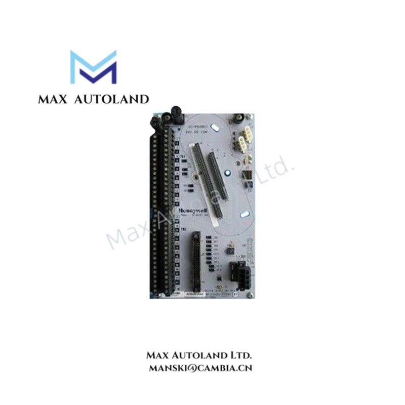
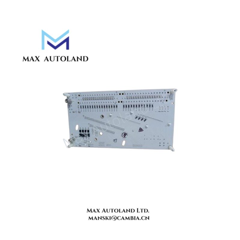
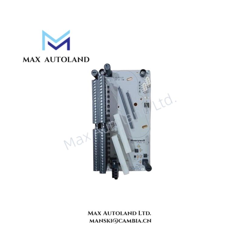
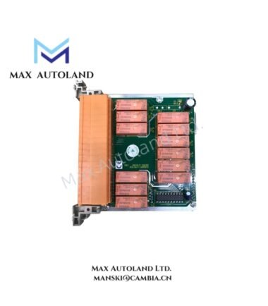
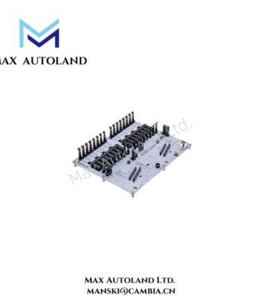
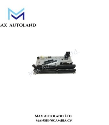
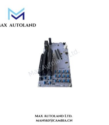
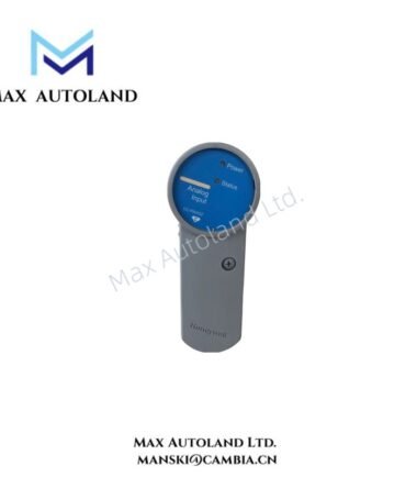
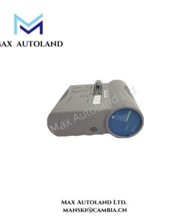
Configured for digital signal acquisition in DCS I/O subsystems, the Honeywell CC-TDIL01 51308386-175 (CC-TDIL01 Digital Input Board) provides direct physical/electrical execution for discrete field signal interfacing across controller I/O architectures.
Suffix Breakdown & Model Matrix
The model identifier CC-TDIL01 51308386-175 represents a cataloged ordering reference for the CC-TDIL01 digital input board assembly. No officially published functional segmentation of suffix elements is provided in the supplied dataset. Functional interpretation should rely on system-level configuration within the host I/O platform.
Hardware Specifications
| Parameter | Specification |
|---|---|
| ModelBrand | Honeywell CC-TDIL01 51308386-175 |
| Origin | USA |
| Weight | 0.38 kg |
| Dimensions | 22 x 12 x 6.8 cm |
| Product Type | Digital Input Board |
| Input Channels | 32 discrete inputs |
| DI Supply Range | 18 to 30 VDC |
| ON Threshold | 13 VDC (min) / 3 mA (min) |
| OFF Threshold | 5 VDC (max) / 1.2 mA (max) |
| Input Filter Delay | 5 ms ± 20% |
| Isolation Method | Optical isolation (IOM level) |
Honeywell Channel Acquisition & Isolation Architecture
The module implements optically isolated discrete input acquisition aligned with Honeywell I/O module design practices. Channel-level signal conditioning is executed through filtered input stages with a nominal 5 ms response delay window. The 18 to 30 VDC input operating envelope supports standard industrial discrete field devices, while threshold discrimination logic ensures defined ON/OFF state separation under low-current sensing conditions. Signal isolation is implemented at the I/O module boundary to reduce electrical coupling between field wiring and system backplane circuitry.
Frequently Asked Questions
Q: Does the module support hot-swap replacement under live backplane conditions?
A: Hot-swap capability is not specified in the provided dataset. Field replacement must follow controller backplane isolation procedures.
Q: What is the effect of the 5 ms input filter delay on fast switching signals?
A: The 5 ms ± 20% filter introduces a deterministic debounce window, suppressing transient pulses shorter than the configured sampling interval.
Q: Is channel-to-channel electrical isolation implemented within the input group?
A: Only optical isolation at the IOM level is specified; per-channel isolation is not defined in the provided technical data.
Field Installation Guidelines
- Ensure field wiring complies with 18 to 30 VDC discrete input range limits.
- Maintain separation between field signal cabling and high-voltage conductors to minimize induced noise.
- Verify correct polarity and common reference configuration before energizing input channels.
- Apply shield grounding at a single-point termination to avoid ground loop formation.
- Confirm module seating integrity in the I/O rack prior to system power-up.


Reviews
There are no reviews yet.