
Overview
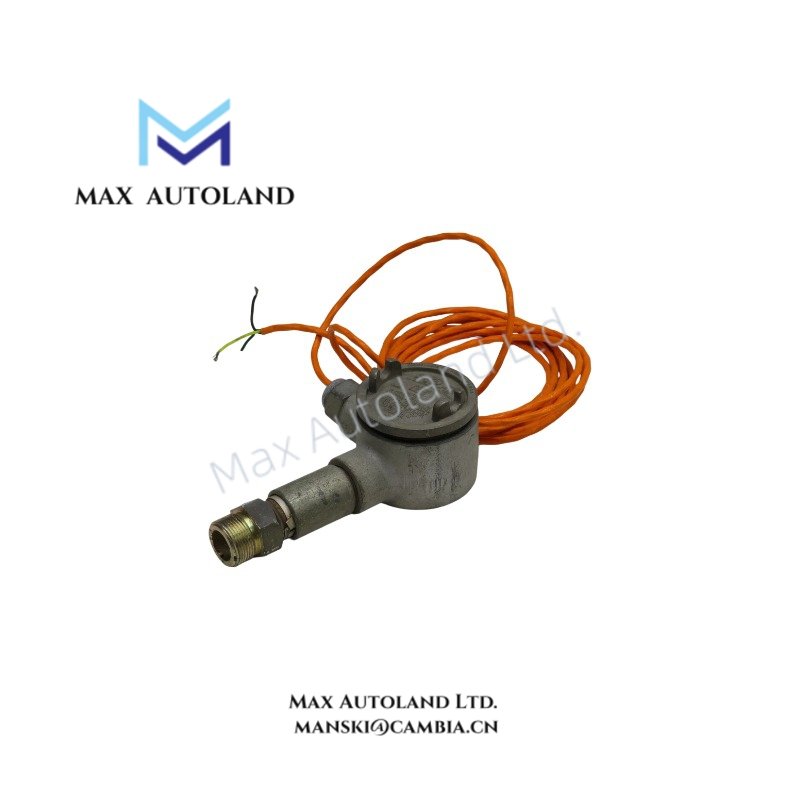
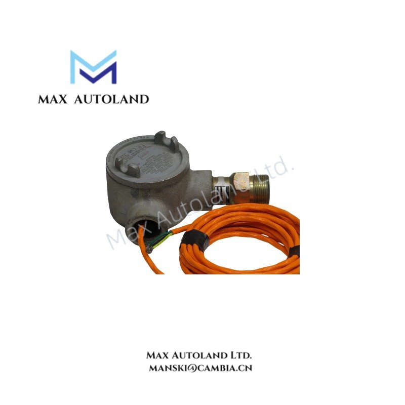
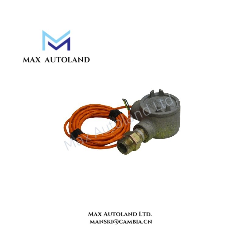
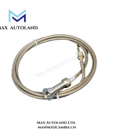
Configured for ultraviolet flame radiation conversion in combustion monitoring loops within gas turbine control systems, the Honeywell LG1093AA04 (LG1093AA04 UV Flame Sensor) provides direct photoelectric detection of UV emissions in the 180–260 nm band and outputs a conditioned signal via remote amplifier interface.
Suffix Breakdown & Model Matrix
No structured suffix segmentation is defined for LG1093AA04. The identifier is treated as a single fixed-order part number without functional option coding disclosed in manufacturer documentation.
Hardware Specifications
| Parameter | Specification |
|---|---|
| ModelBrand | Honeywell LG1093AA04 |
| Origin | USA |
| OperatingTemp | -40 degF to +350 degF |
| PowerConsumption | Not specified (dependent on external amplifier configuration) |
| Detection Principle | Ultraviolet (UV) flame radiation sensing |
| Spectral Range | 180–260 nm (solar blind region) |
| Response Time | < 0.1 s |
| Supply Voltage | 20–35 VDC or 115 VAC (via amplifier interface) |
| Transmission Distance | Up to 1000 ft sensor-to-amplifier |
| Pressure Rating | 150 psig at 400 degF |
| Mounting Interface | 3/4 in internal NPT |
| Cable Interface | Teflon-shielded, 1 in conduit thread |
Honeywell Process Instrumentation Signal Conditioning Interface Behavior
The LG1093AA04 operates through a remote UV detection head coupled to a signal conditioning amplifier stage typical of Honeywell combustion monitoring architectures. The interface path is designed for low-level phototube pulse acquisition and subsequent conversion into a deterministic control signal suitable for integration with DCS or turbine control logic. Channel integrity is maintained via shielded cabling and galvanic separation between sensing element and control electronics, minimizing noise coupling in high electromagnetic interference turbine environments.
Frequently Asked Questions
Q: Does the sensor output a direct 4–20 mA signal?
A: No direct 4–20 mA output is generated at the sensing head. Signal conversion is performed in an external amplifier or control module.
Q: What limits the maximum sensor-to-amplifier distance?
A: Distance is constrained by cable attenuation, shielding integrity, and amplifier input sensitivity; system rating specifies up to 1000 ft.
Q: Is the UV detection band susceptible to infrared interference?
A: No. The 180–260 nm spectral window is outside infrared emission range, reducing IR cross-sensitivity.
Field Installation Guidelines
Sensor mounting shall maintain direct optical line-of-sight to the combustion zone with minimized obstruction from refractory surfaces. Use 3/4 in NPT engagement with appropriate thread sealing compound rated for high temperature service. Teflon-shielded cable routing must avoid parallel runs with high-voltage ignition conductors to reduce capacitive coupling noise. Maintain continuous shield grounding at amplifier end only to prevent ground loop formation. Ensure optical window remains free of carbon deposits or particulate buildup to preserve UV transmission characteristics.



Reviews
There are no reviews yet.