



Overview
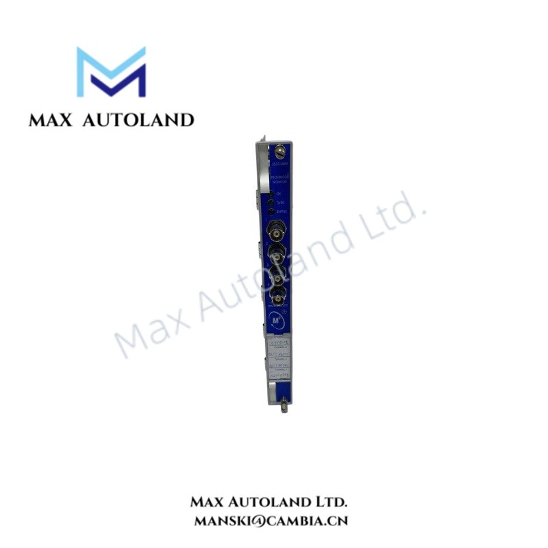
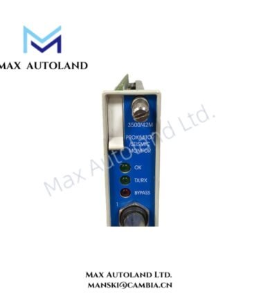
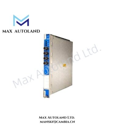
Configured for proximity transducer signal conditioning and machinery measurement in the Bently Nevada 3500 Machinery Protection System, the Bently Nevada 3500/40M (3500/40M Proximitor Monitor) processes up to four proximity transducer inputs and evaluates conditioned values against programmable alarm setpoints.
Hardware Specifications
| Parameter | Specification |
|---|---|
| Model | 3500/40M |
| Brand | Bently Nevada |
| Product Type | 4-Channel Proximitor Monitor Module |
| System | 3500 Machinery Protection System |
| Origin | Not specified in the supplied data |
| Signal Channels | 4 channels; accepts 1 to 4 proximity transducer signals |
| Input Impedance | 10 kOhm, standard I/O |
| Transducer Power Supply | -24 VDC |
| Power Consumption | 7.7 W typical |
| Radial Vibration Scaling | 3.94 mV/um (100 mV/mil) or 7.87 mV/um (200 mV/mil) |
| Thrust Position Scaling | 3.94 mV/um (100 mV/mil) or 7.87 mV/um (200 mV/mil) |
| Eccentricity Scaling | 3.94 mV/um (100 mV/mil) or 7.87 mV/um (200 mV/mil) |
| Differential Expansion Scaling | 0.394 mV/um (10 mV/mil) or 0.787 mV/um (20 mV/mil) |
| REBAM Scaling | 40 mV/um (1000 mV/mil) or 80 mV/um (2000 mV/mil) |
| Measurement Accuracy | +/-0.33% of full scale typical; +/-1% maximum |
| Direct Filter | User programmable, 4 Hz to 4000 Hz or 1 Hz to 600 Hz |
| Gap Filter | -3 dB at 0.09 Hz |
| Vector Filters | 1X and 2X Constant Q filters |
| Alarm Setpoints | Independent Alert and Danger setpoints |
| Alarm Delay | User programmable |
| Front Panel Indicators | OK, TX/RX, and Bypass LEDs |
| Buffered Outputs | Front-panel coaxial connectors for raw transducer signal access; short-circuit protected and unbuffered |
| Operating Temp | -30 deg C to +65 deg C |
| Storage Temp | -40 deg C to +85 deg C |
| Humidity | Up to 95%, non-condensing |
| Dimensions | 241.3 mm x 24.4 mm x 241.8 mm main board |
| Weight | Approximately 0.91 kg |
Eddy-Current Probe Scaling and Gap Voltage
The 3500/40M processes signals from Bently Nevada proximity transducers and applies measurement-specific scaling for radial vibration, thrust position, eccentricity, differential expansion, and REBAM functions. Therefore, probe type, target geometry, cable configuration, and monitor scaling must match the configured measurement range.
For eddy-current probe installation, verify the probe gap voltage before commissioning the measurement channel. A typical Bently Nevada installation uses a nominal -10 VDC target gap condition, subject to the specific probe and transducer system configuration. Proper gap validation also helps prevent incorrect displacement scaling and unwanted alarm behavior.
The monitor supports programmable direct filtering and vector filtering. Consequently, engineers can select frequency response characteristics appropriate for the monitored rotor dynamics and measurement function.
Frequently Asked Questions
Q: How many proximity transducer channels does the 3500/40M provide?
A: The monitor provides 4 signal channels and accepts 1 to 4 proximity transducer signals.
Q: What transducer supply voltage does the monitor provide?
A: The supplied specification identifies a -24 VDC transducer power supply.
Q: Can the 3500/40M monitor different machinery measurements?
A: Yes. Channel pairs can be configured for radial vibration, thrust position, differential expansion, eccentricity, or REBAM measurements.
Field Installation Guidelines
- Install the module in the designated 3500 rack position and verify rack compatibility before energization.
- Use the specified Bently Nevada proximity transducer, extension cable, and interface arrangement for the selected measurement.
- Verify probe polarity, field wiring continuity, and transducer supply voltage before connecting the monitoring channel.
- Check the probe gap voltage during commissioning and confirm that the measured value matches the required transducer setup.
- Route proximity signal cables separately from high-current power wiring, contactor wiring, and other high-noise circuits.
- Maintain appropriate cable shielding and grounding practices according to the 3500 system installation documentation.
- Confirm probe orientation, target condition, mechanical clearance, and shaft reference before enabling alarm functions.
- Verify the configured measurement scaling against the actual probe sensitivity and monitored mechanical variable.
- Check Alert and Danger setpoints after configuration, then confirm the programmed alarm delay behavior.
- Use the front-panel coaxial outputs for diagnostic signal observation without disturbing the primary transducer wiring.
- Confirm OK, TX/RX, and Bypass status indicators during commissioning and functional testing.
- Do not remove or replace the module while energized unless the installed 3500 rack configuration and maintenance procedure explicitly permit the operation.



Reviews
There are no reviews yet.