


Overview
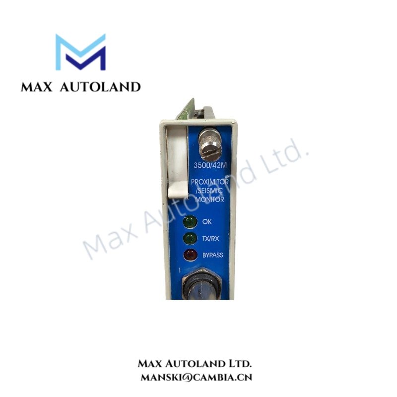
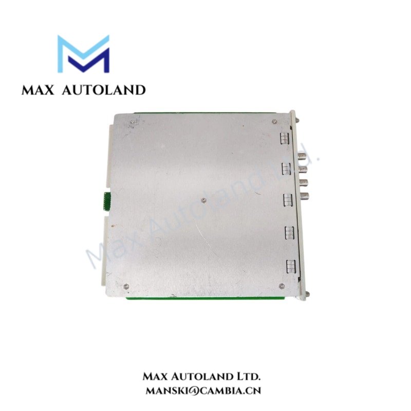
Configured for proximity and seismic signal conditioning in the Bently Nevada 3500 Machinery Protection System, the Bently Nevada 3500/42M (3500/42M Proximitor Seismic Monitor) processes four transducer channels. It conditions vibration and position signals, applies programmable alarm setpoints, and provides buffered and recorder outputs for monitoring circuits.
Hardware Specifications
| Parameter | Specification |
|---|---|
| Model | 3500/42M |
| Brand | Bently Nevada |
| Product Type | 4-channel Proximitor Seismic Monitor |
| System | Bently Nevada 3500 Machinery Protection System |
| Origin | Not specified in the supplied data |
| Channel Count | 4 channels |
| Channel Configuration | Channels operate in pairs; each pair supports one monitoring function |
| Supported Transducers | Proximity probes, acceleration transducers, velocity transducers, seismoprobes |
| Input Impedance | 10 kOhm for standard Proximitor and acceleration inputs |
| Buffered Transducer Outputs | Front-panel coaxial connector for each channel |
| Buffered Output Impedance | 550 Ohm |
| Buffered Output Protection | Short-circuit protected |
| Recorder Output | +4 to +20 mA proportional to monitor full-scale |
| Recorder Load | 0 to 600 Ohm |
| Transducer Power Supply | -24 VDC |
| Programmable Functions | Radial Vibration, Thrust Position, Differential Expansion, Eccentricity, REBAM, Acceleration and Velocity, Shaft Absolute, Circular Acceptance Region |
| Dimensions | 241.3 mm x 24.4 mm x 241.8 mm |
| Dimensions, Imperial | 9.50 in x 0.96 in x 9.52 in |
| Weight | 0.91 kg |
| Power Consumption | 7.7 W typical |
| Operating Temperature | Not specified in the supplied data |
| Front-Panel Indicators | OK, TX/RX, Bypass |
Mechanical Monitoring and Signal Scaling
The 3500/42M processes dynamic signals from proximity and seismic transducers and converts them into programmable machinery-monitoring measurements. Each channel pair can execute one selected monitoring function, while the two channel pairs can operate with identical or different functions.
For proximity-probe applications, technicians should validate the probe gap voltage before commissioning the measurement channel. A typical Bently Nevada eddy-current probe installation uses a nominal -10 VDC gap target, subject to the applicable probe system specification and measurement range.
The module supports measurement functions associated with rotor dynamics, including radial vibration, thrust position, differential expansion, eccentricity, and shaft absolute measurements. It also supports acceleration and velocity measurements for seismic or accelerometer-based monitoring.
Furthermore, the front-panel buffered outputs provide direct access to conditioned transducer signals. The recorder outputs provide +4 to +20 mA signals proportional to the configured monitor full-scale value.
Frequently Asked Questions
Q: How does the 3500/42M organize its four monitoring channels?
A: The four channels operate as two channel pairs. Each pair can be configured for one monitoring function, and the two pairs can use identical or different functions.
Q: What transducer types can the 3500/42M accept?
A: The supplied data specifies compatibility with proximity probes, acceleration transducers, velocity transducers, and seismoprobes.
Q: Does the module provide direct access to the transducer signals?
A: Yes. Each channel provides a front-panel buffered transducer output through a coaxial connector. The specified output impedance is 550 Ohm, with short-circuit protection.
Field Installation Guidelines
- Install the module in the designated 3500 rack position and verify correct mechanical seating before energizing the rack.
- Confirm that the selected I/O module matches the intended transducer type and channel configuration.
- Verify proximity-probe wiring polarity and inspect the probe extension cable and connections before commissioning.
- For eddy-current probe channels, measure and validate the probe gap voltage against the applicable transducer system specification.
- Route low-level transducer cables separately from high-current power conductors and switching circuits to reduce electromagnetic coupling.
- Maintain cable shielding according to the applicable Bently Nevada installation practice and site grounding standard.
- Verify the recorder output load before connecting external monitoring or recording equipment.
- Check the OK, TX/RX, and Bypass LEDs after rack startup to confirm module status and communication activity.
- Confirm channel configuration and alarm setpoints with the approved 3500 Rack Configuration Software configuration before placing the protection system in service.









Reviews
There are no reviews yet.