
Overview
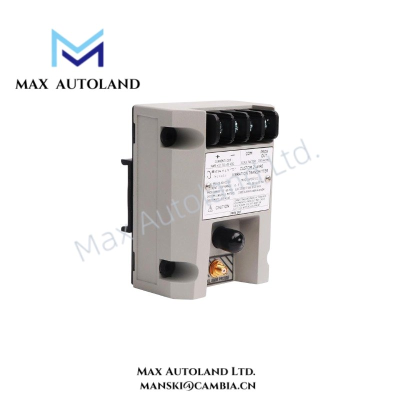
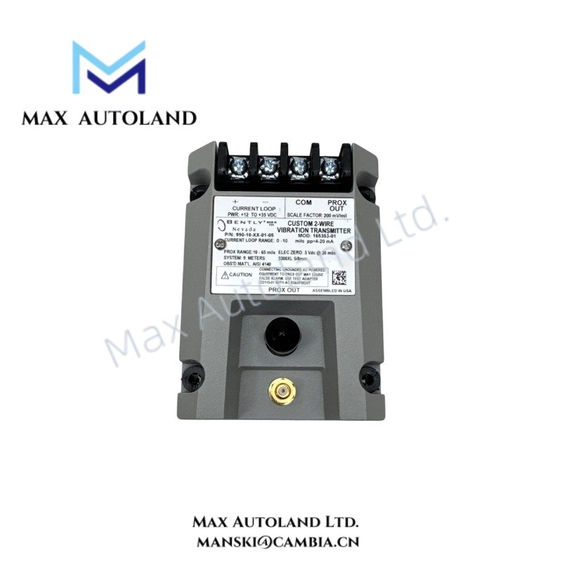
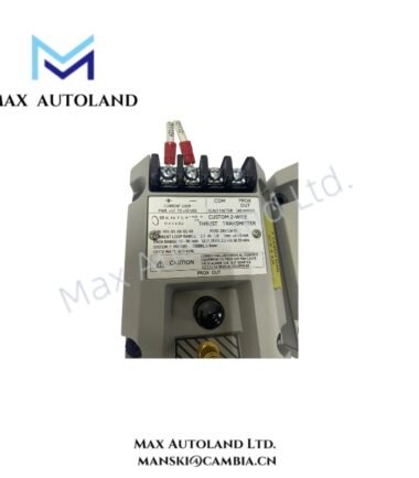
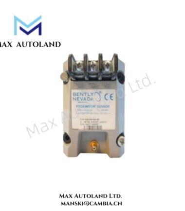
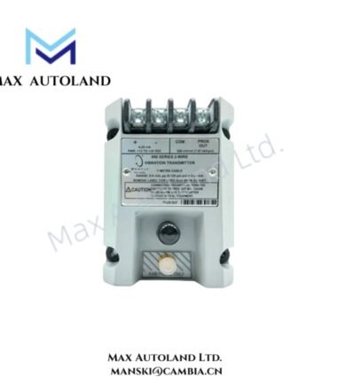
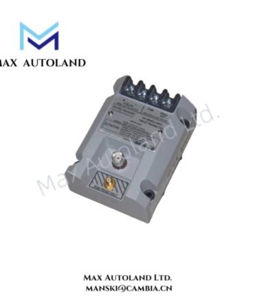
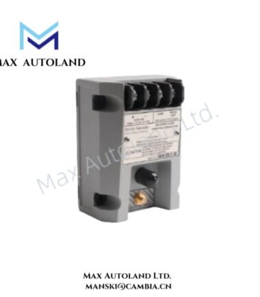
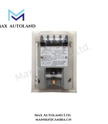
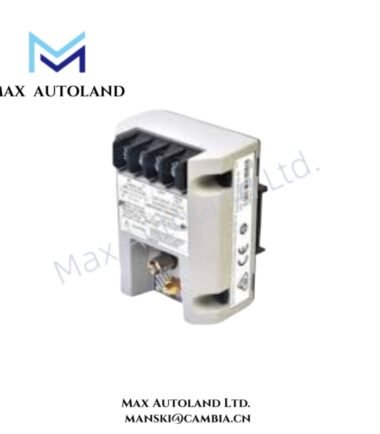
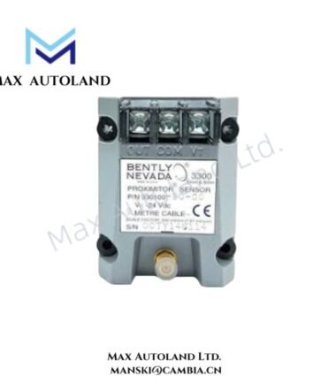
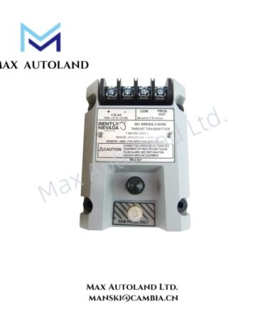
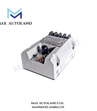
The Bently Nevada 990-10-XX-01-05, also cataloged as the 990-10 Vibration Transmitter, converts vibration probe signals into a continuous vibration measurement for machinery monitoring. The unit uses a 5.0 meter or 7.0 meter system length and supports a 0-10 mils pp (0-250 um pp) full-scale range.
Suffix Breakdown & Model Matrix
| Code | Specification |
|---|---|
| 10 | 0-10 mils pp (0-250 um pp) full-scale vibration range |
| 50 | 5.0 meters (16.4 feet) system length |
| 70 | 7.0 meters (23.0 feet) system length |
| 01 | 35 mm DIN rail clips |
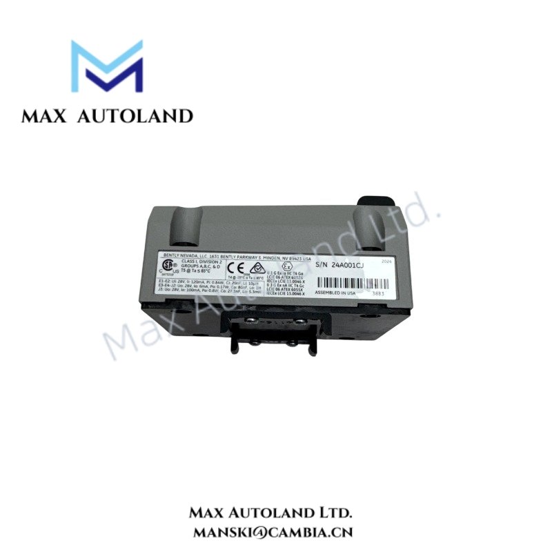
| 05 | CSA Division 2, ATEX Zone 0, ATEX Zone 2, and ABS maritime approval |
The supplied model 990-10-XX-01-05 identifies the 990-10 Vibration Transmitter configuration. The input data provides alternative system-length codes 50 and 70, while the exact value represented by XX is not explicitly defined.
Hardware Specifications
| Parameter | Specification |
|---|---|
| Model | 990-10-XX-01-05 |
| Brand | Bently Nevada |
| Product Type | Vibration Transmitter |
| Origin | USA |
| Weight | 0.5 kg |
| Dimensions | Estimated shipping size: 7.4 x 5.8 x 10 cm |
| Power Consumption | Requires +12 to +35 VDC input at transmitter terminal |
| Full-scale Range | 0-10 mils pp (0-250 um pp) |
| System Length Options | 5.0 meters / 7.0 meters |
| Mounting | 35 mm DIN rail clips |
| Agency Approval | CSA Division 2, ATEX Zone 0, ATEX Zone 2, ABS maritime approval |
| Tariff Code | 8537101190 |
| Shipment Location | Xiamen, China |
Eddy-Current Probe Scaling and Vibration Signal Processing
The 990-10 transmitter operates within a Bently Nevada machinery vibration monitoring arrangement. It scales the connected vibration measurement to a defined full-scale range of 0-10 mils pp (0-250 um pp).
The selected system length must match the installed probe and cable configuration. Therefore, the 5.0 meter and 7.0 meter options should not be interchanged without confirming the complete measurement-chain requirements.
The transmitter requires +12 to +35 VDC at its terminals. Installers should maintain correct polarity and verify the available supply voltage before energizing the device.
Frequently Asked Questions (FAQ)
Q: What vibration range does the 990-10-XX-01-05 support?
A: The supplied configuration specifies a 0-10 mils pp (0-250 um pp) full-scale vibration range.
Q: What power supply does the transmitter require?
A: The transmitter requires a +12 to +35 VDC input applied at the transmitter terminal.
Q: How is the transmitter mounted?
A: This configuration specifies 35 mm DIN rail clips for mechanical mounting.
Field Installation Guidelines
- Verify the transmitter model and complete system-length configuration before installation.
- Confirm the DC supply polarity and measure the supply voltage before connecting the transmitter.
- Install the unit on a mechanically secure 35 mm DIN rail.
- Route vibration signal wiring separately from high-current power conductors where practical.
- Use appropriate cable shielding practices for low-level vibration signals and terminate shields according to the plant grounding standard.
- Keep probe and transmitter wiring away from strong electromagnetic interference sources.
- Confirm the selected 5.0 meter or 7.0 meter system length against the installed measurement chain.
- Check the applicable CSA, ATEX, and ABS installation requirements when installing equipment in classified or maritime applications.
- Do not infer an operating-temperature limit from the supplied shipping dimensions or approval information.
Reviews
There are no reviews yet.