
Overview
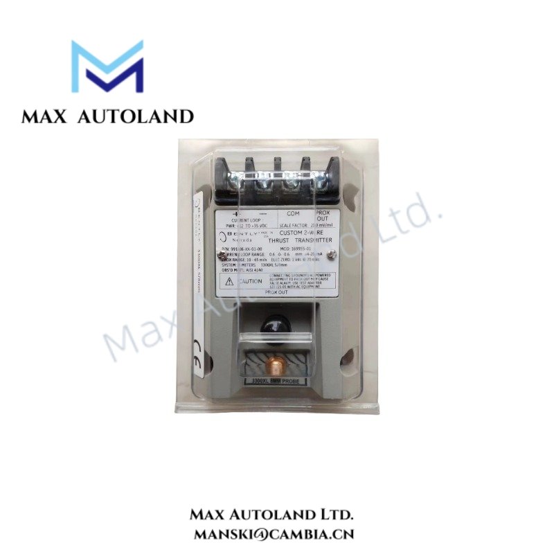
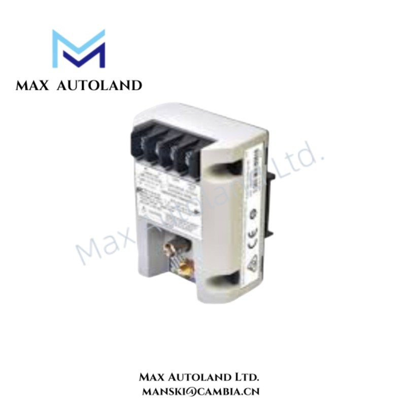
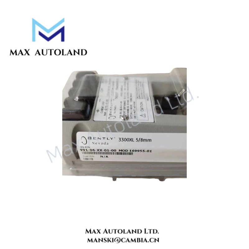
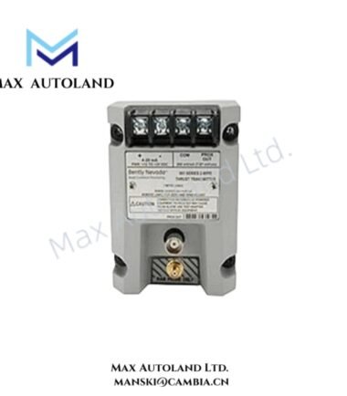
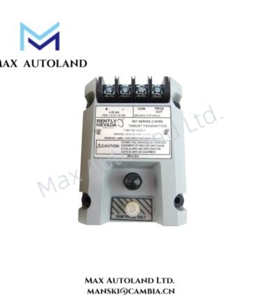
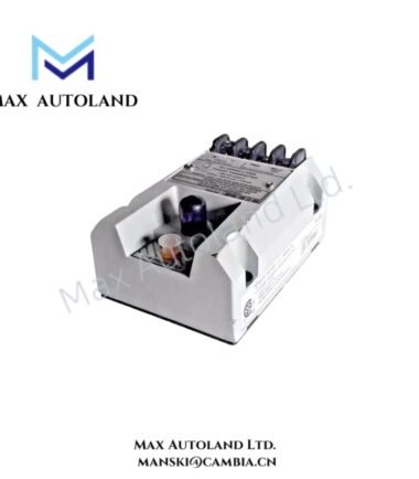
Configured for axial shaft position measurement in rotating machinery, the Bently Nevada 991-06-XX (991 Thrust Transmitter) accepts a 3300 NSv proximity probe signal and converts the measured thrust position into a 4-20 mA loop signal for PLC, DCS, or machinery monitoring interfaces.
Hardware Specifications
| Parameter | Specification |
|---|---|
| Model | 991-06-XX |
| Brand | Bently Nevada |
| Product Type | 2-Wire Loop-Powered Thrust Transmitter |
| Measurement Function | Shaft axial position / thrust position |
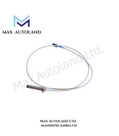
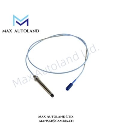
| Input Device | One Bently Nevada 3300 NSv non-contacting proximity probe |
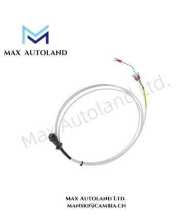
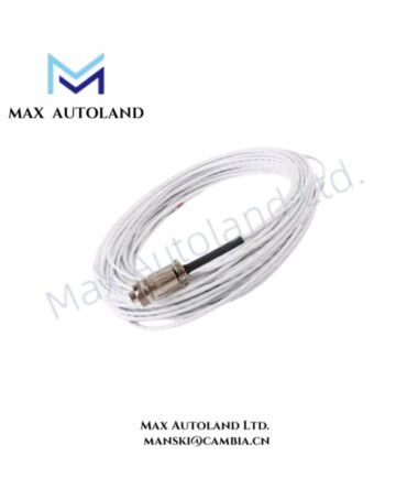
| Extension Cable | Matching 3300 NSv extension cable; 5 m or 7 m system length |
| Power Supply | +12 to +35 VDC at transmitter terminals |
| Output | 4-20 mA DC, 2-wire loop-powered |
| Measurement Range | Up to 1.2 mm or 50 mils, depending on configuration |
| Loop Accuracy | Within +/- 1.5% of specified full-scale range |
| Maximum Loop Resistance | 1,000 ohms at 35 VDC, including cable resistance |
| Current Limiting | 23 mA typical |
| Zero and Span | Non-interacting external adjustments |
| Prox Out Scale Factor | 7.87 mV/um or 200 mV/mil, +/- 6.5% typical |
| Prox Out Linear Range | 0.25 mm to 1.65 mm |
| Typical Current Loop Ranges | 0-0.6 mm or 25-0-25 mils |
| Temperature Stability | Scale factor remains within +/- 10% of nominal from 0 deg C to +70 deg C |
| Mounting | DIN-rail clips or bulkhead mounting screws |
| Construction | Fully potted enclosure |
| Humidity Capability | Up to 100% condensing humidity |
| Diagnostics | PROX OUT and COM terminals plus coaxial test connector |
| Operating Temperature | 0 deg C to +70 deg C specified for scale-factor stability; broader operating range not specified |
| Power Consumption | Loop-powered; exact consumption not specified in supplied data |
| Approvals | CSA/NRTL/C general purpose and VDE; hazardous-area configurations depend on suffix |
Eddy-Current Probe Scaling and Rotor Dynamics
The 991-06-XX processes the AC and DC components from a Bently Nevada 3300 NSv eddy-current proximity probe system. The transmitter scales probe displacement into a current-loop output that represents axial shaft position.
The Prox Out circuit provides an incremental scale factor of 7.87 mV/um, equivalent to 200 mV/mil, with a typical tolerance of +/- 6.5% across the specified linear range. Therefore, technicians can verify probe gap and transmitter scaling through the available test connections.
For machinery commissioning, the probe installation should establish the specified electrical gap before the transmitter enters normal measurement service. In addition, technicians should evaluate rotor axial position relative to the thrust bearing reference position rather than interpreting the 4-20 mA signal as a generic vibration value.
The transmitter also incorporates a Power-up Inhibit circuit. This circuit suppresses unwanted startup transients while the measurement loop establishes its operating condition. Furthermore, the Not OK / Signal Defeat function prevents selected abnormal probe or connection conditions from producing inappropriate protection-system responses.
Frequently Asked Questions
Q: What proximity probe does the 991-06-XX accept?
A: The transmitter accepts one Bently Nevada 3300 NSv non-contacting proximity probe with a matching extension cable. The specified complete system cable length is 5 m or 7 m.
Q: What electrical signal does the transmitter provide?
A: The device provides a 4-20 mA DC, 2-wire loop-powered output. The transmitter requires +12 to +35 VDC at its terminals.
Q: How can technicians verify the probe signal?
A: Technicians can use the non-isolated PROX OUT and COM terminals and the coaxial connector to check dynamic signal behavior and probe gap voltage during commissioning and troubleshooting.
Field Installation Guidelines
- Install the transmitter using the specified DIN-rail clips or bulkhead mounting screws.
- Connect the 3300 NSv probe and matching extension cable according to the applicable Bently Nevada wiring arrangement.
- Maintain correct probe polarity and signal connections before applying loop power.
- Verify the probe mechanical installation and electrical gap before relying on the 4-20 mA output.
- Route the probe cable separately from high-current motor, power, and switching conductors where practical to reduce electrical interference.
- Maintain appropriate cable shielding and grounding practices for the complete monitoring circuit. Avoid creating unintended ground loops.
- Confirm that the external zero and span adjustments correspond to the required axial-position range before placing the transmitter into service.
- Verify the 4-20 mA loop resistance against the available supply voltage. The specified maximum loop resistance is 1,000 ohms at 35 VDC, including cable resistance.
- Use the PROX OUT, COM, and coaxial test connections for commissioning measurements without disturbing the primary loop wiring.
- After installation, verify normal startup behavior and confirm that the Power-up Inhibit and Not OK / Signal Defeat functions operate as intended within the connected monitoring or control system.


Reviews
There are no reviews yet.