
Overview
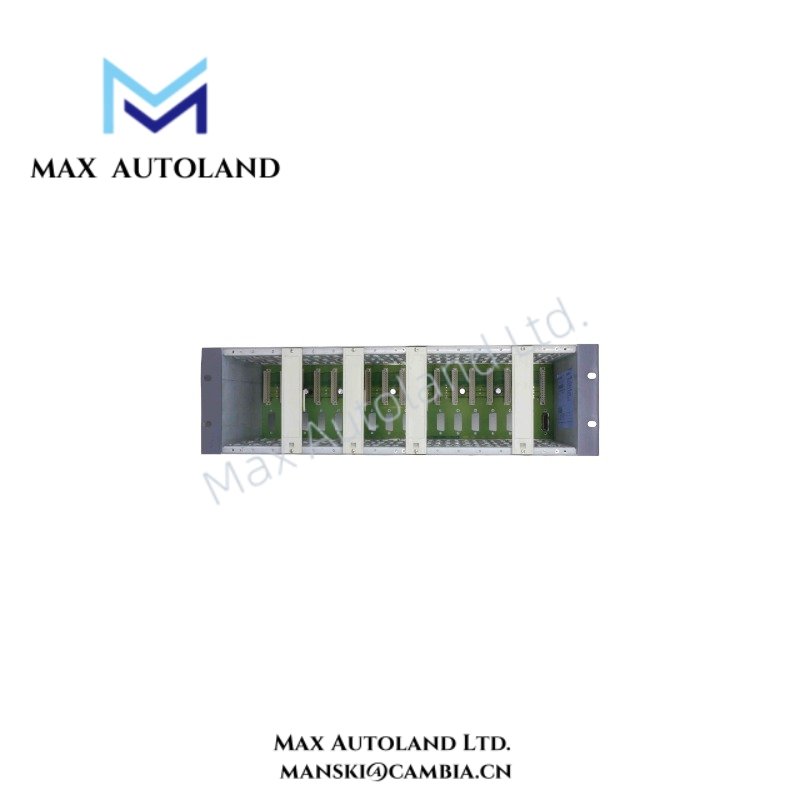
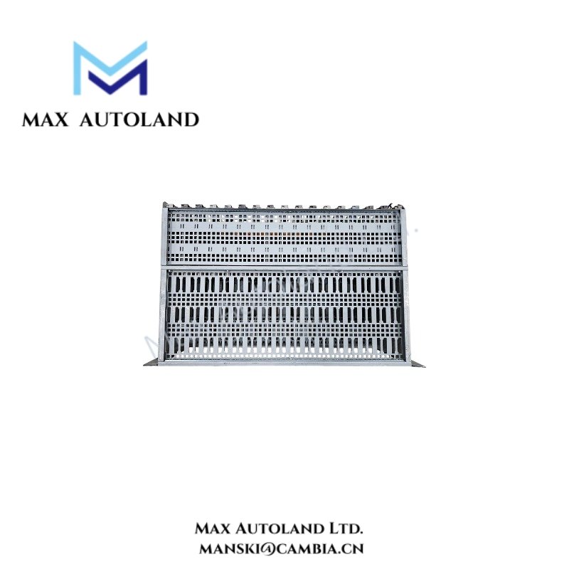
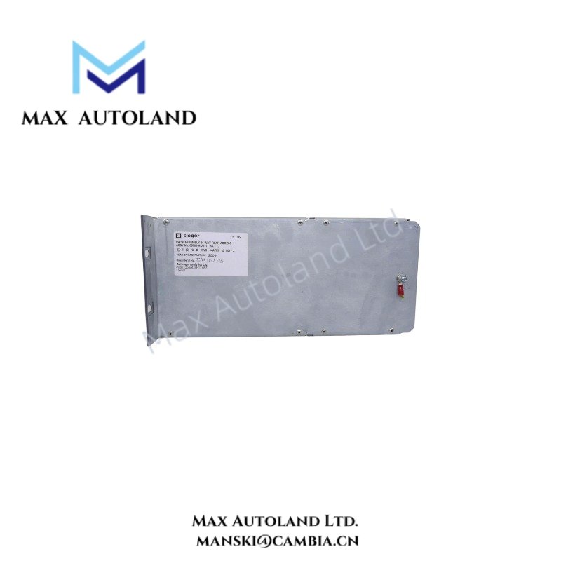
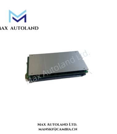
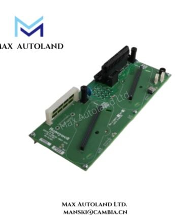
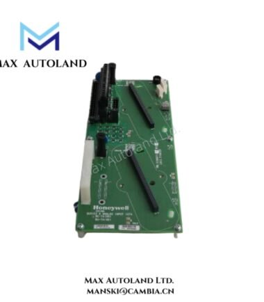
Configured for centralized card-based signal aggregation in System 57 gas and fire monitoring architecture, the Honeywell 05701-A-0511 (05701-A-0511 rack assembly) provides a 19 inch subrack platform for electrical backplane distribution and multi-slot controller card mounting within Honeywell System 57 hardware nodes.
Suffix Breakdown & Model Matrix
No validated manufacturer-published suffix decomposition is available for 05701-A-0511. The identifier is treated as a fixed configuration rack assembly code within the System 57 mechanical catalog structure. No functional sub-variant segmentation is defined in the provided technical dataset.
Hardware Specifications
| Parameter | Specification |
|---|---|
| Model | 05701-A-0511 |
| Brand | Honeywell |
| Origin | USA (System 57 platform manufacturing lineage) |
| Weight | Not specified |
| Dimensions | 19 inch rack, 3U height, up to 17 slot architecture |
| Product Type | Rack Assembly / Subrack Backplane Frame |
| Slot Capacity | Up to 17 card slots |
| Backplane Interface | System 57 proprietary backplane interconnect |
| Wiring Access | Rear field termination interface |
| Supply Voltage | System dependent (commonly 24 VDC architecture in System 57 nodes) |
Honeywell Process Control Backplane Architecture Characteristics
Within Honeywell System 57 process I/O architecture, rack assemblies such as 05701-A-0511 implement a distributed backplane electrical topology supporting card-to-card communication segregation. Signal conditioning, engineering interface, and field termination paths are electrically partitioned across the rack plane to reduce shared impedance coupling between measurement input channels. Typical System 57 implementations maintain loop-level separation consistent with industrial 4-20 mA signal domain handling and digital control card isolation boundaries, enabling independent module insertion without cross-channel electrical disturbance at the backplane bus level.
Frequently Asked Questions (FAQ)
Q: Can individual control cards be removed without disturbing backplane wiring continuity?
A: The rack supports modular insertion/removal at slot level; backplane continuity is maintained per slot design, while field wiring remains terminated at rear interface blocks.
Q: What is the electrical load contribution of the rack backplane itself?
A: Backplane consumption is not defined as a fixed value; total current draw is determined by installed card configuration and System 57 power distribution module capacity.
Q: Does the rack impose any communication bus dependency between adjacent slots?
A: Slot architecture supports parallel backplane distribution; inter-slot dependency is defined by installed engineering and control cards rather than the mechanical rack itself.
Field Installation Guidelines
The 05701-A-0511 rack assembly shall be mounted in a standard 19 inch cabinet with fixed mechanical support at both front rack ears. Maintain continuous protective earth bonding between rack chassis and cabinet frame. Backplane alignment must remain free of mechanical stress during card insertion. Field wiring termination should be routed to rear terminal assemblies with segregation between low-level signal lines and relay or power conductors. Cable shielding shall be terminated at a single-point ground reference within the cabinet structure to prevent loop impedance formation across the backplane reference plane.




Reviews
There are no reviews yet.