



Overview
Suffix Breakdown & Model Matrix
The supplied documentation identifies 103928-02 as a single catalog number. No official suffix matrix or option code breakdown is specified for this model.
Hardware Specifications
| Parameter | Specification |
|---|---|
| Model | 103928-02 |
| Spare Model | Series 2150/2155 |
| Brand | Bently Nevada |
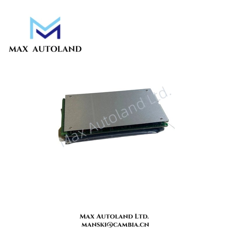
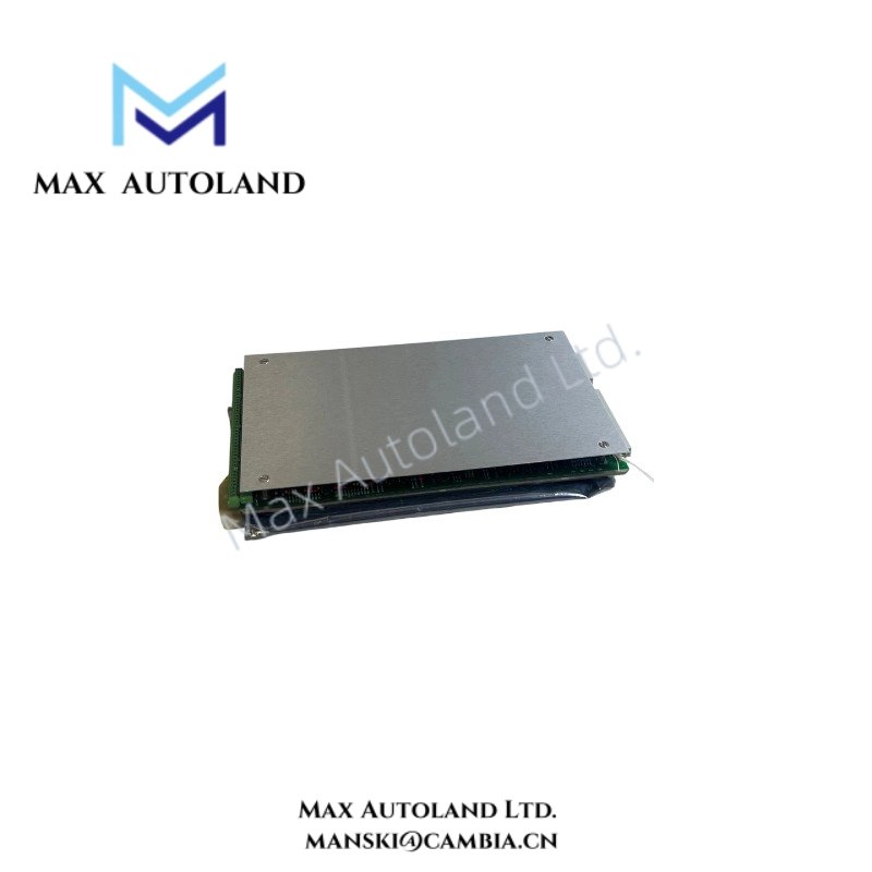
| Product Type | Transient Data Interface Module |
| Associated Board | Keyphasor (KPH) Input Board |
| Primary Function | Transient data interface and Keyphasor signal processing |
| System Compatibility | Bently Nevada Series 2150/2155 |
| Origin | USA |
| Weight | 0.7 kg |
| Dimensions | 2.5 cm x 19.1 cm x 34.3 cm |
| Operating Temp | Not specified |
| Power Consumption | Not specified |
Keyphasor Synchronization and Rotor Dynamic Measurement
The 103928-02 interfaces with the Keyphasor input path to establish rotational reference information required during transient data acquisition. The Keyphasor signal provides shaft position synchronization for waveform capture, phase analysis, orbit generation, and rotor dynamic evaluation.
Proper probe installation includes verification of eddy-current probe scaling and confirmation of the probe gap voltage. For Bently Nevada proximity measurement systems, a target gap voltage near -10 VDC is commonly used during commissioning to verify that the probe operates within its linear measurement range. Shielded signal wiring and appropriate cable separation help reduce cross-talk between Keyphasor and vibration channels.
Frequently Asked Questions
Q: Can the 103928-02 be installed or removed while system power is applied?
A: The available documentation does not specify hot-swap capability. Module replacement should follow the maintenance procedure defined for the associated Series 2150/2155 system.
Q: What is the purpose of the Keyphasor input connection?
A: The Keyphasor input supplies a once-per-revolution or multiple-per-revolution reference signal used for phase synchronization, transient recording, shaft orbit analysis, and other rotor dynamic measurements.
Q: Does the module contain configurable operating parameters?
A: Configuration depends on the host monitoring system and associated software. No onboard configuration details are provided in the supplied specifications.
Field Installation Guidelines
- Verify that the module part number matches the intended Series 2150/2155 installation location before insertion.
- Disconnect system power or follow the approved maintenance procedure before installing or removing the module if hot replacement is not documented.
- Route Keyphasor and vibration signal cables separately from high-voltage or high-current conductors to minimize electromagnetic interference.
- Connect cable shields according to the system grounding specification to reduce electrical noise and prevent ground loop formation.
- Confirm probe gap voltage and Keyphasor signal integrity during commissioning before initiating transient data collection.
- Inspect backplane connectors for contamination or mechanical damage before module installation.







Reviews
There are no reviews yet.