
Overview
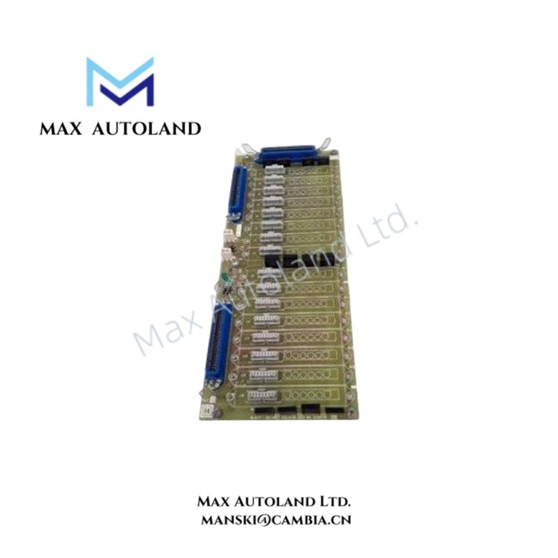
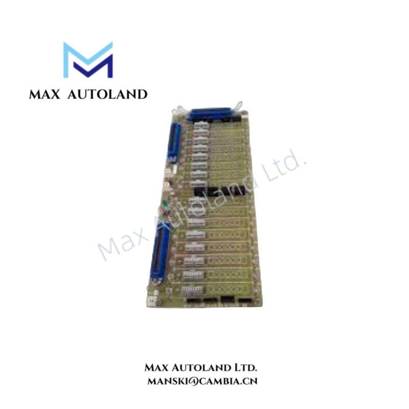
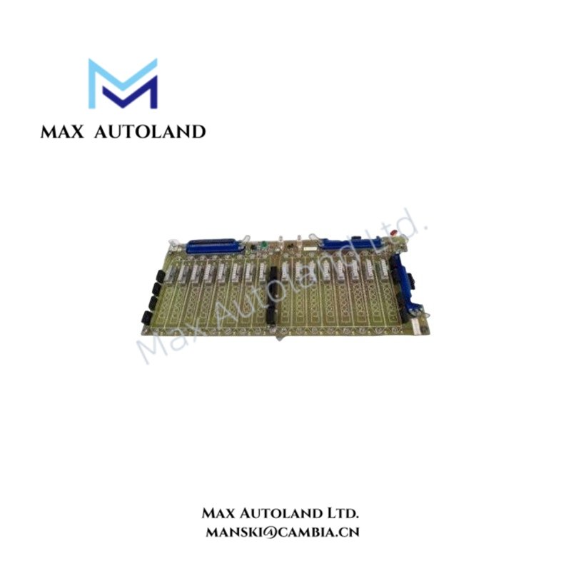
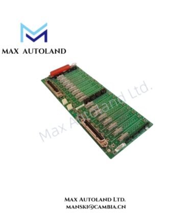
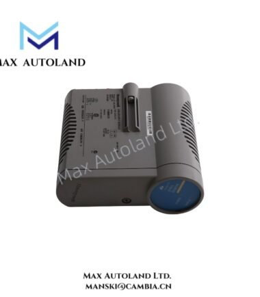
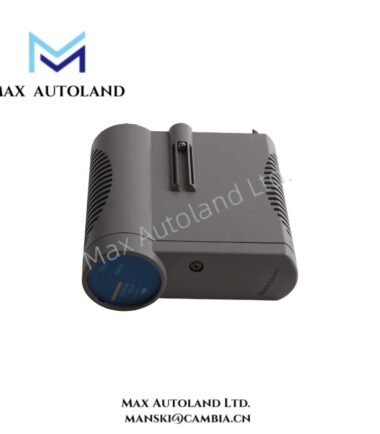
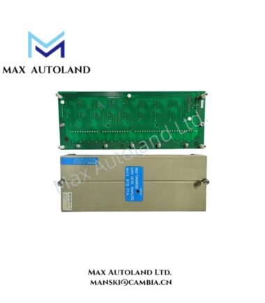
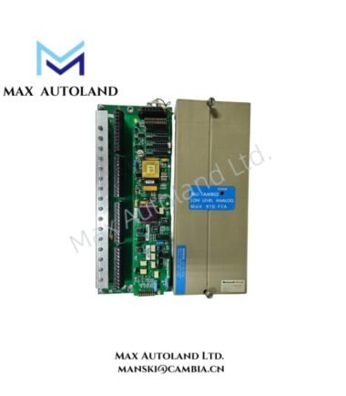
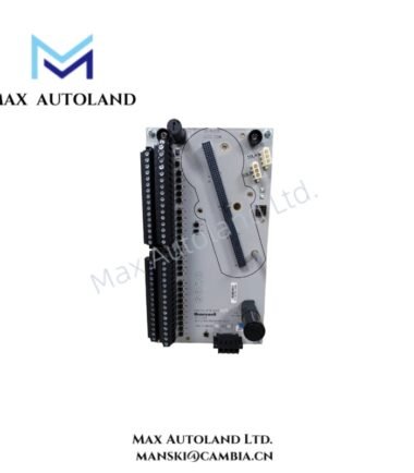
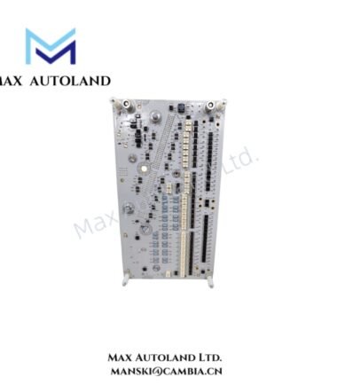
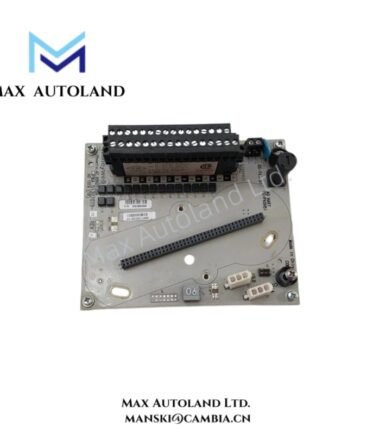
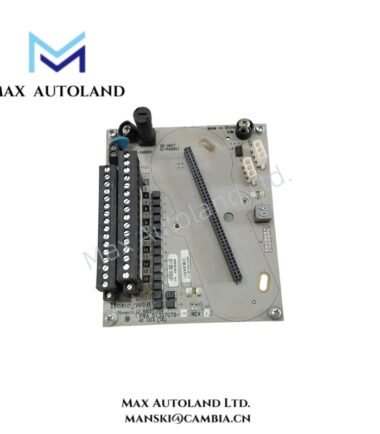
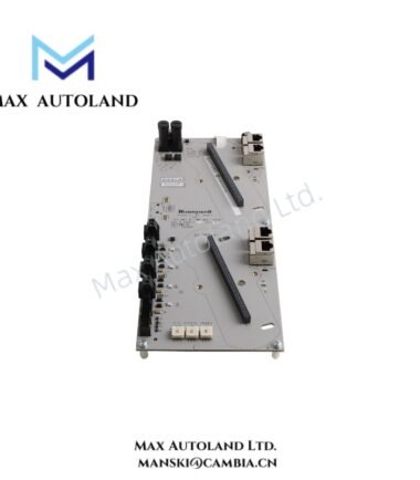
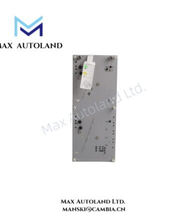
Configured for analog field signal acquisition in Honeywell control system environments, the Honeywell MU-GAIH13 51304718-100 (MU-GAIH13 Analog Input Module) provides electrical interfacing between process instrumentation and the control system.
Hardware Specifications
| Parameter | Specification |
|---|---|
| Model | MU-GAIH13 |
| Part Number | 51304718-100 |
| Brand | Honeywell |
| Product Type | Analog Input Module |
| Application Platform | Honeywell Experion PKS / TDC 3000 environments |
| Input Signal Types | Industrial analog current or voltage signals; 4-20 mA or 0-10 V examples |
| Input Impedance | Approximately 100 kOhm for voltage input |
| Supply / Loop Power | 24 VDC |
| Current Consumption | 100 mA |
| Mounting | Modular control cabinet installation; mounting arrangement depends on the associated Honeywell hardware |
| Operating Environment | Standard industrial temperature and humidity conditions |
| Certification | CE |
Honeywell Process Signal Interface
The MU-GAIH13 handles analog field signals for acquisition by a Honeywell control system. In particular, the supplied data identifies support for 4-20 mA and 0-10 V signal types.
For current-loop applications, the module interfaces the field circuit with the control-system input path. For voltage signals, the stated input impedance is approximately 100 kOhm. The module also supports 24 VDC loop or system power and has a specified current consumption of 100 mA.
Where the associated installation uses HART-enabled 4-20 mA instrumentation, verify HART compatibility at the complete channel and termination level before commissioning. Likewise, confirm channel-to-channel isolation requirements against the applicable Honeywell system documentation rather than assuming isolation from the module designation alone.
Frequently Asked Questions (FAQ)
Q: What field signal types are identified for the MU-GAIH13?
A: The supplied specifications identify standard industrial analog signals, including 4-20 mA current and 0-10 V voltage signals.
Q: What power supply information is specified?
A: The supplied data specifies 24 VDC loop or system power support and a current consumption of 100 mA.
Q: Does the supplied data confirm hot-swapping capability?
A: No. The supplied information does not specify hot-swap capability. Follow the applicable Honeywell installation procedure before removing or inserting the module under power.
Field Installation Guidelines
- Verify the exact Honeywell chassis, carrier, termination assembly, and system revision before installation.
- Confirm the field signal type and wiring polarity before connecting the analog input circuit.
- Route analog signal wiring separately from high-voltage and high-current conductors where practical.
- Use shielded instrumentation cable where the installation specification requires electromagnetic noise control.
- Terminate cable shields according to the plant grounding and Honeywell system wiring specification.
- Verify the 24 VDC supply voltage and circuit polarity before energizing the module.
- Check terminal tightness and conductor identification before commissioning.
- Do not assume isolation, hot-swap operation, or HART pass-through capability unless the applicable hardware documentation confirms it.
- Perform channel verification using the configured input range and the control-system engineering database before placing the point into service.


Reviews
There are no reviews yet.