
Overview
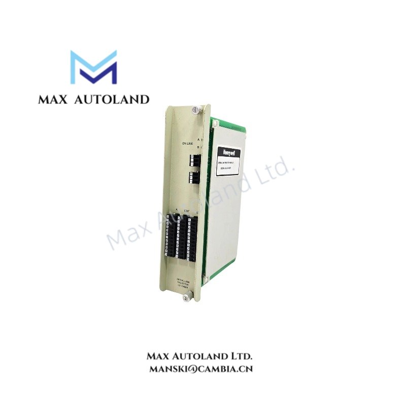
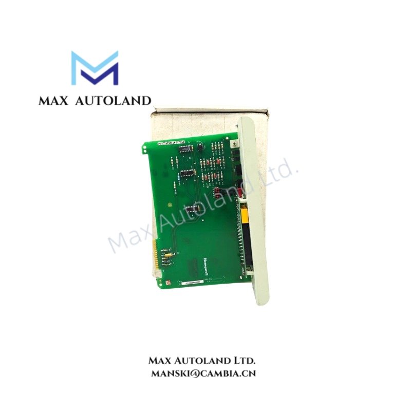
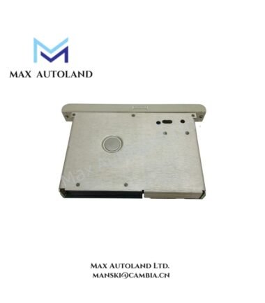
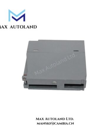
Configured for regulated DC distribution to backplane-mounted I/O logic assemblies in IPC 621 Logic Manager architectures, the Honeywell 621-9932 (621-9932 Power Supply Module) provides direct electrical execution of +5 VDC logic power and ±15 VDC auxiliary rails within rack-based industrial control chassis.
Suffix Breakdown & Model Matrix
No formal suffix segmentation is defined for this orderable module. The identifier 621-9932 represents a single hardware configuration with fixed electrical and mechanical characteristics. No embedded functional variant codes are specified by manufacturer documentation.
Hardware Specifications
| Parameter | Specification |
|---|---|
| Model | Honeywell 621-9932 |
| Brand | Honeywell |
| Origin | Not specified |
| Weight | Approx. 2.27 kg |
| PowerConsumption | 96 VA (max input) |
| Input Voltage | 20 to 28 VDC (nominal 24 VDC) |
| Logic Output | +5 VDC, 8 A |
| Auxiliary Output | +15 VDC / -15 VDC, 600 mA |
| Surge Current | 40 A (cold start max) |
| Protection | Front-access fuse (8 A fast-blow) |
| Mounting | Rack-mounted IPC 621 I/O chassis |
Honeywell Process Control Power Distribution Characteristics
The module implements regulated backplane power conversion for Honeywell IPC 620 / IPC 621 I/O structures, with internal regulation stages supporting stable +5 VDC logic rail generation under dynamic load conditions. Channel-to-channel electrical isolation is applied within the power conversion topology to reduce cross-loading effects across mixed analog and digital I/O assemblies. The design supports transient suppression during cold-start inrush events, limiting downstream backplane disturbance during rack energization sequences.
Frequently Asked Questions
Q: Can the 621-9932 be hot-swapped under load conditions?
A: Hot-swap capability is not specified for this module. Removal under energized backplane conditions may result in transient disruption of +5 VDC logic rails across installed I/O cards.
Q: What is the impact of cold start surge on rack backplane stability?
A: The module draws up to 40 A during inrush. This transient is internally limited but must be considered when multiple rack power modules share a common 24 VDC supply bus.
Q: Does the auxiliary ±15 VDC output operate independently from the +5 VDC logic rail?
A: Yes. The ±15 VDC auxiliary outputs are derived from a separate regulation stage and remain electrically decoupled from the primary +5 VDC logic supply domain.
Field Installation Guidelines
Ensure the 24 VDC input source is current-rated for inrush conditions exceeding 40 A per module. Maintain low-impedance grounding between rack chassis and system protective earth. Do not route input power conductors parallel to low-level analog signal lines within the same cable tray. Verify fuse integrity (8 A fast-blow type) prior to energization. Install module fully seated into IPC 621 backplane connector to ensure stable bus engagement and prevent intermittent logic rail dropouts.






Reviews
There are no reviews yet.