
Overview
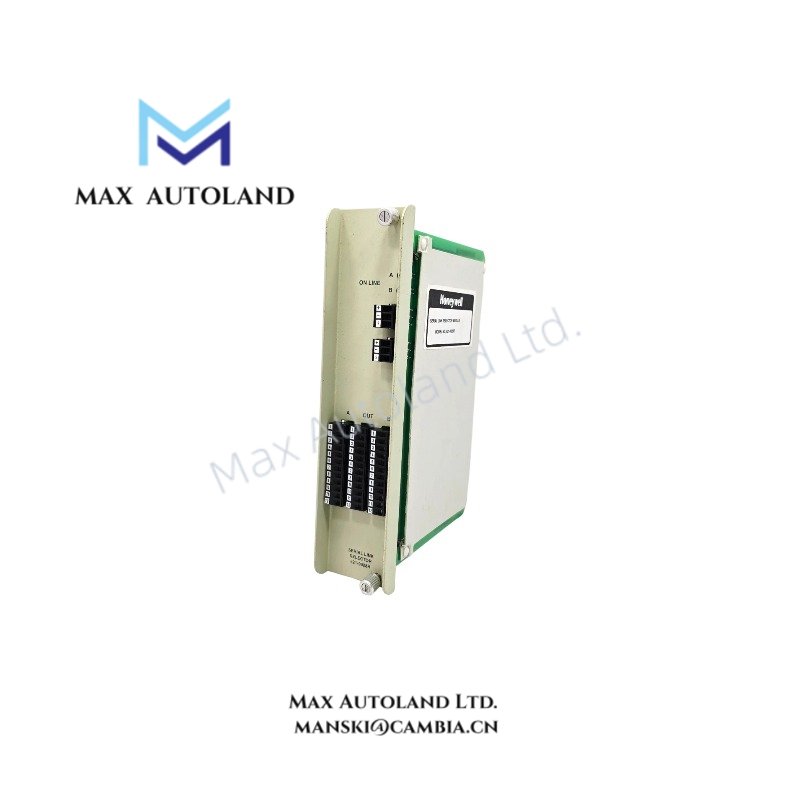
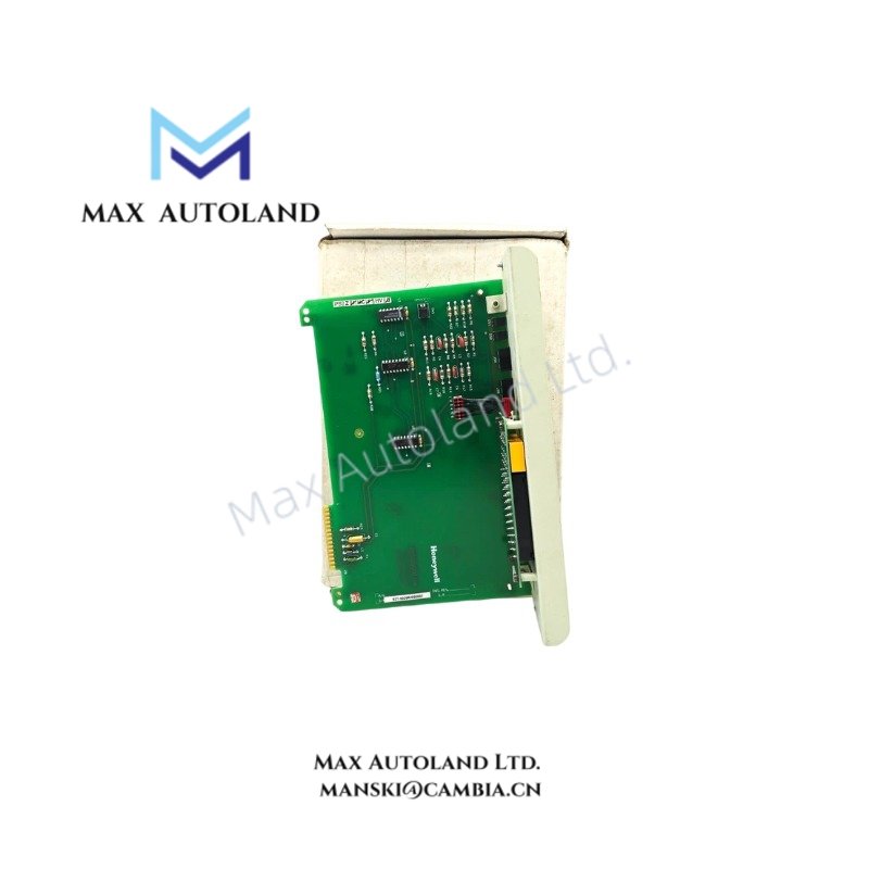
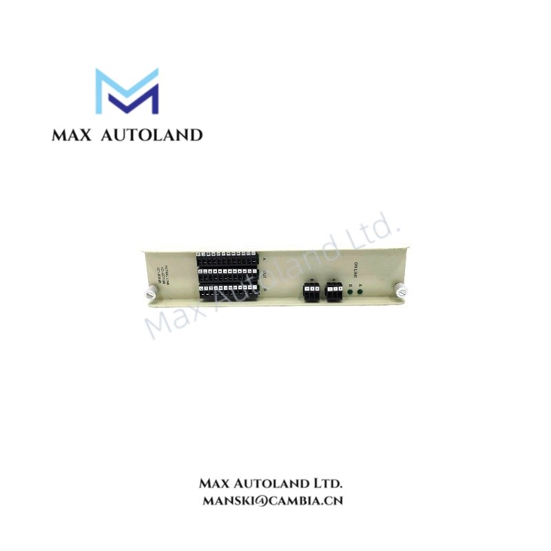
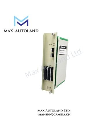
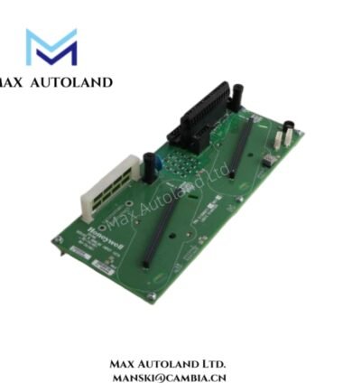
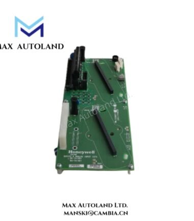
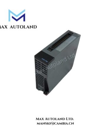
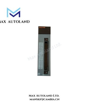
The Honeywell 621-9928R, also cataloged as the 621-9928R Serial Link Selector Module, operates as a dedicated hardware component for serial communication routing within the IPC-620 / Logic Manager system architecture. It executes physical switching and distribution of RS-232 and RS-485 data streams between PLC, HMI, and field interface nodes without protocol translation.
Suffix Breakdown & Model Matrix
- 621: IPC-620 series hardware family identifier
- 9928: Serial link selector functional block designation
- R: Revision / hardware variant suffix
No additional documented segmentation or functional coding beyond manufacturer assignment is available for this part number.
Hardware Specifications
| Parameter | Specification |
|---|---|
| Model | 621-9928R |
| Brand | Honeywell |
| Weight | 460 g to 500 g |
| Dimensions | Not specified |
| OperatingTemp | -25 degC to 75 degC |
| PowerConsumption | Max 7 W |
| Power Supply | 24 VDC +/-10% |
| Communication Interfaces | 2 x RS-232, 2 x RS-485 |
| Baud Rate | Up to 256 kbps |
| Isolation | 2000 VDC galvanic isolation |
| Termination | Dual 12-position detachable terminal blocks |
Honeywell Process Communication Channel Isolation Characteristics
The 621-9928R implements fixed galvanic isolation barriers rated at 2000 VDC between communication domains to prevent ground loop propagation across distributed serial segments. Within Honeywell process control architectures, channel separation logic is typically aligned with multi-segment signal integrity preservation, where RS-232 point-to-point links and RS-485 multidrop buses coexist under a shared backplane routing scheme. Isolation boundaries are enforced at hardware level, ensuring that transient voltage differentials do not propagate into upstream Logic Manager processing nodes. The module does not perform protocol conversion; all routing is electrically deterministic based on selector logic state.
Frequently Asked Questions
Q: Does the 621-9928R support hot-swapping under live RS-485 bus conditions?
A: The module is not designed for hot insertion on active communication buses. Field practice requires bus de-energization or controlled segmentation before hardware replacement to prevent transient line disruption.
Q: What is the effect of full port utilization on backplane power consumption?
A: Power draw remains bounded by the 7 W maximum specification. Load distribution is internal and does not scale linearly with port activity, as switching logic is passive-deterministic.
Q: Can RS-232 and RS-485 channels operate simultaneously?
A: Yes. Electrical domains are isolated, allowing concurrent operation of all four communication channels without cross-protocol interference.
Field Installation Guidelines
- Install on standard industrial DIN rail within IPC-620 compatible enclosure systems
- Maintain separation between RS-485 twisted pair routing and power conductors to minimize inductive coupling
- Ensure shield termination at a single grounding point per segment to avoid loop current formation
- Verify 24 VDC supply stability prior to energizing communication backplane
- Avoid exceeding recommended cable length limits for RS-485 multidrop segments to preserve signal integrity
- Perform continuity check across terminal blocks before system integration



Reviews
There are no reviews yet.