

Overview
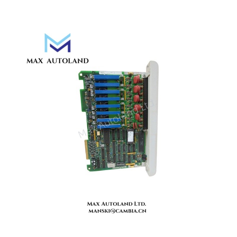
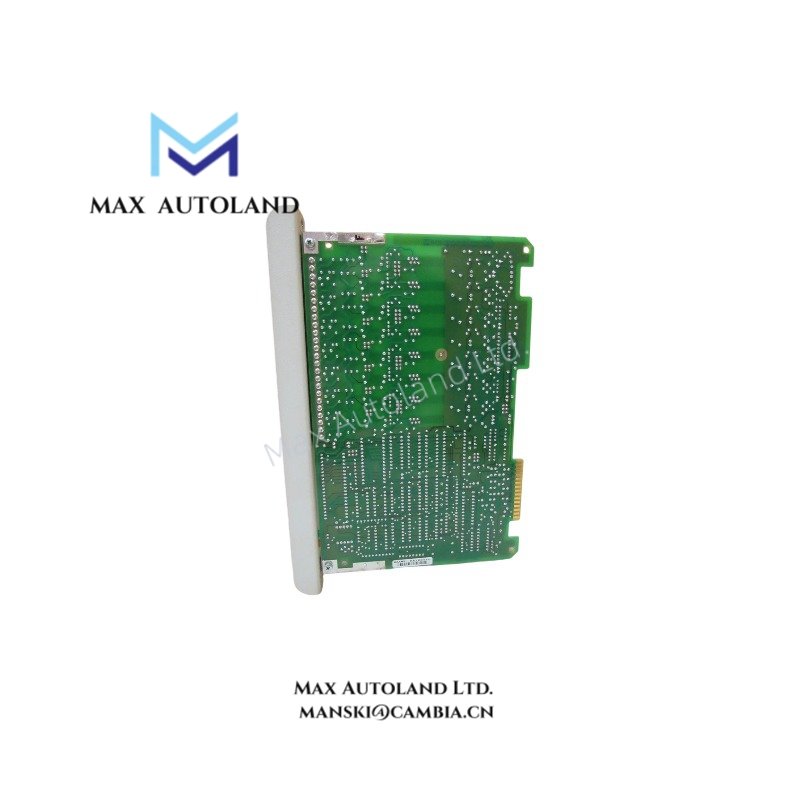
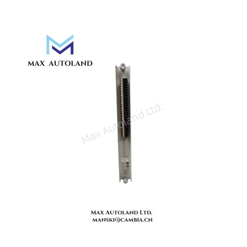
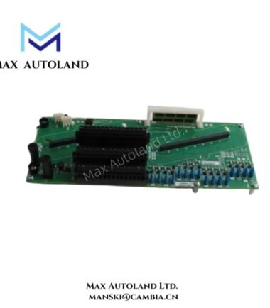
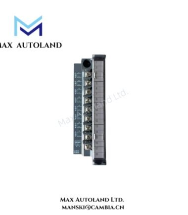
The Honeywell 621-0022-RC, also cataloged as the 621-0022 Digital Input Module, operates as a dedicated hardware component for monitoring discrete field contact states within Honeywell IPC 620/621 programmable controller systems.
Hardware Specifications
| Parameter | Specification |
|---|---|
| Model | 621-0022-RC |
| Brand | Honeywell |
| Origin | USA |
| Weight | Approx. 0.25 kg |
| Dimensions | Standard single-slot IPC rack width |
| Operating Temp | 0 deg C to 60 deg C |
| Power Consumption | Low backplane power draw (typical < 2 W) |
| Input Voltage | 24 VDC nominal (18–30 VDC range) |
| Channels | 16 isolated inputs |
| Isolation | Optical isolation, 1500 VAC field/logic |
| Indicators | Per-channel LEDs, module health LED |
| Mounting | IPC 620/621 rack compatible |
Channel-to-Channel Isolation and Backplane Bus Behavior
The module supports channel-to-channel isolation characteristics consistent with distributed process control I/O design. Each input group interfaces directly with the backplane bus using deterministic scan cycles. This configuration minimizes crosstalk between discrete signals while maintaining synchronization with the IPC processor scan table.
Frequently Asked Questions
Q: Does the 621-0022-RC support hot-swap replacement?
A: Yes. The module is designed for live insertion in compatible IPC 620/621 racks without interrupting system power, provided rack firmware supports online I/O reconfiguration.
Q: What is the expected backplane current load per module?
A: Typical backplane current consumption is below 200 mA at 5 VDC logic supply levels.
Q: Are input channels individually fused?
A: No. External overcurrent protection must be provided at the field wiring level; the module relies on optical isolation for internal circuit protection.
Field Installation Guidelines
Install the module into a grounded IPC 620/621 rack using correct ESD handling procedures. Ensure all field wiring is terminated on the removable terminal block before insertion. Maintain separation between high-voltage power conductors and input signal wiring to reduce inductive coupling. Verify shield drain wires are connected to chassis ground at one point only. Confirm input voltage remains within the 18–30 VDC range prior to energizing the rack.




Reviews
There are no reviews yet.