

Overview
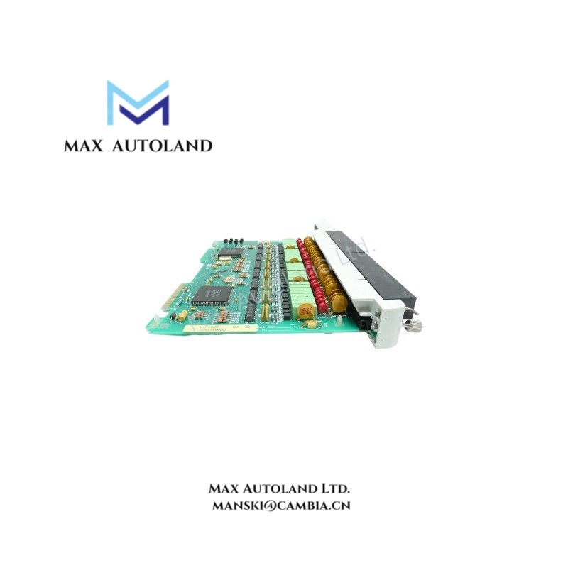
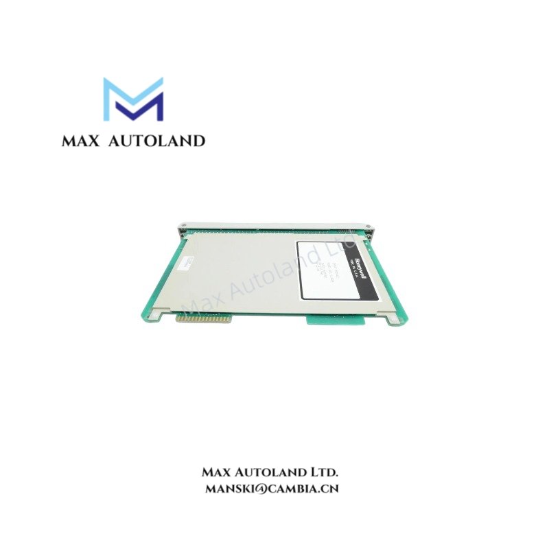
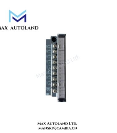
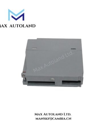
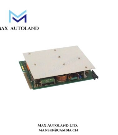
Configured for discrete signal acquisition in the Honeywell IPC 620 manufacturing automation system, the Honeywell 621-1180R (621-1180 Digital Input Module) provides direct physical/electrical execution by converting 120 VAC/VDC field device states into isolated logic levels for CPU processing.
Hardware Specifications
| Parameter | Specification |
|---|---|
| Model | 621-1180R |
| Brand | Honeywell |
| Origin | Webster, NY, USA |
| Weight | 0 lbs 9.6 oz (0.3 kg) |
| Dimensions | 1.3 in x 9.4 in x 7.0 in (3.3 cm x 23.9 cm x 17.8 cm) |
| Operating Temp | 0 deg C to 60 deg C (32 deg F to 140 deg F) |
| Storage Temp | -40 deg C to 85 deg C (-40 deg F to 185 deg F) |
| Humidity | 5% to 95% RH (non-condensing) |
| Channels | 16 Channels (Group Isolated) |
| Rated Input Voltage | 120 VAC/VDC |
| Input Voltage Range | 85 V to 132 VAC / 90 V to 150 VDC |
| Signal Frequency | 47 Hz to 63 Hz (AC) |
| Isolation | Optical Isolation, 1500 VAC minimum (Field to Logic) |
| Status Indicators | Front Panel LEDs per Channel and Module Health |
| Wiring Connection | Removable Terminal Block |
| Cooling | Natural Convection / Passive |
Backplane Bus Communication and Channel Density Scaling
The module interfaces with the IPC 620 backplane via a parallel data bus, transferring 16 bits of discrete status data per scan cycle. Channel density scaling is optimized for high-density racks, allowing full population without exceeding backplane current budgets. The removable terminal block facilitates rapid replacement without rewiring, maintaining consistent bus termination impedance during module swaps.
Frequently Asked Questions
Q: Does the “R” suffix indicate support for hot-swap operations?
A: Yes. The 621-1180R is engineered for redundant configurations. The design allows module replacement under power in high-availability systems, provided proper lockout/tagout procedures are followed for the specific field wiring circuits.
Q: What is the typical backplane power consumption for thermal load calculation?
A: The module draws low current from the backplane 5 VDC and 24 VDC rails. For rack cooling and power supply sizing, refer to the IPC 620 system manual for the exact milliamp values per channel group.
Q: How is optical isolation verified during commissioning?
A: Verify isolation by measuring resistance (> 1 megohm) between field input terminals and the module’s logic ground reference point while the module is de-energized.
Field Installation Guidelines
Mount the module into the designated IPC 620 chassis slot until the ejector levers fully seat. Ensure the removable terminal block is disengaged before installation. Torque field wiring screws to the manufacturer’s specification (typically 7-9 lb-in). Route high-voltage input wiring separate from communication cables to prevent inductive coupling. Verify input voltage polarity for DC applications prior to applying power to the module.





Reviews
There are no reviews yet.