
Overview
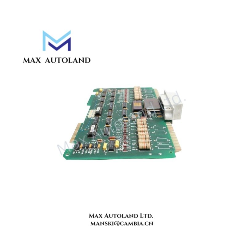
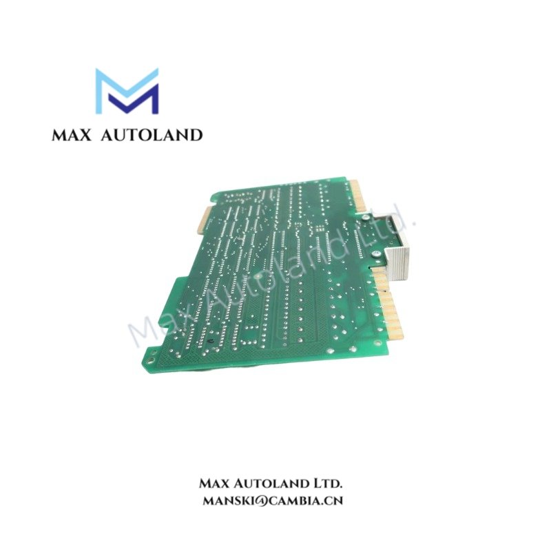
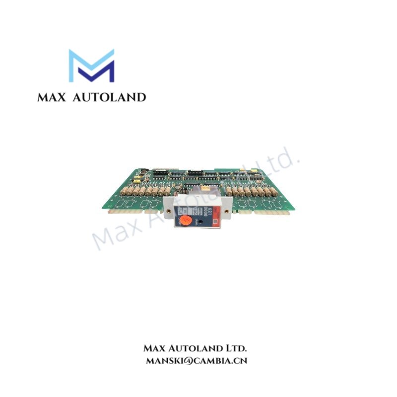
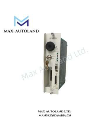
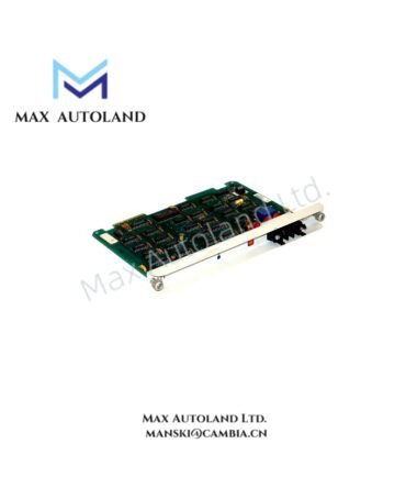
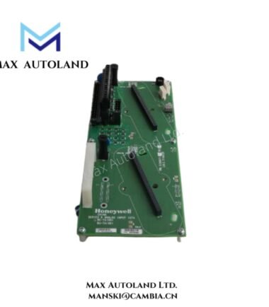
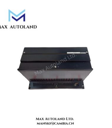
Configured for Specific Technical Task in System/Network Name, the Honeywell 621-0000 (621-0000 Analog Input Module) provides direct physical/electrical execution. The hardware module interfaces external field instrumentation with the IPC 620 centralized logic processor, converting analog field data into discrete digital values for register storage.
Hardware Specifications
| Parameter | Specification |
|---|---|
| Model | 621-0000 |
| Brand | Honeywell |
| Origin | United States |
| Weight | 0.4 kg |
| Dimensions | 2.9 cm x 23.9 cm x 17.3 cm |
| Operating Temp | 0 to 60 degC |
| Power Consumption | Backplane dependent |
| System Compatibility | IPC 620 Universal I/O System |
| Primary Task | Control, Communication, Monitoring |
Process Control and DCS Instrumentation
The module interfaces with multi-channel field networks to ingest analog variables. It supports standard 4-20 mA HART loop protocol architectures, ensuring steady-state signal integration without data corruption over long-distance topologies. Input-to-logic architecture relies on robust channel-to-channel isolation to prevent ground loop currents from destabilizing adjacent processing channels or the internal system backplane. For thermal element integration, embedded cold junction compensation (CJC) maintains voltage measurement linearity across variable ambient operating environments.
Frequently Asked Questions
Q: Does the 621-0000 module support hot-swap capabilities during active backplane operations?
A: No. Removing or inserting this module while the IPC 620 chassis is energized can cause backplane voltage fluctuations, risking component damage or unexpected logic states. Power down the rack chassis before installation or removal.
Q: How is the channel-to-channel isolation rated on this hardware?
A: The module utilizes optical isolation to decouple field-side loops from the logic-side backplane, preventing high-voltage transients from migrating to the processing core.
Field Installation Guidelines
- Chassis Alignment: Slide the module smoothly along the chassis card guides until the wedge connectors fully seat into the active backplane socket. Secure the module retention screws to ensure a continuous frame ground contact.
- Shield Grounding: Terminate all instrumentation cable shields at a single, designated low-impedance ground point near the enclosure entry panel. Do not ground the shield at both ends to prevent the formation of ground loops.
- Wiring Separation: Route low-voltage analog signal lines in separate conduits away from high-voltage AC power lines or inductive motor drive cables to prevent electromagnetic cross-talk.





Reviews
There are no reviews yet.