
Overview
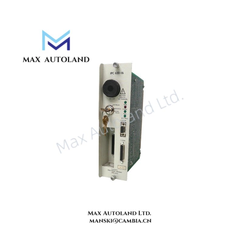
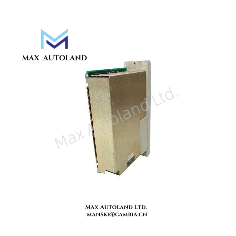
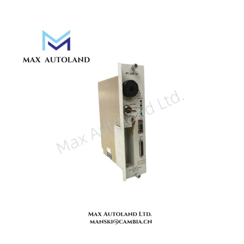
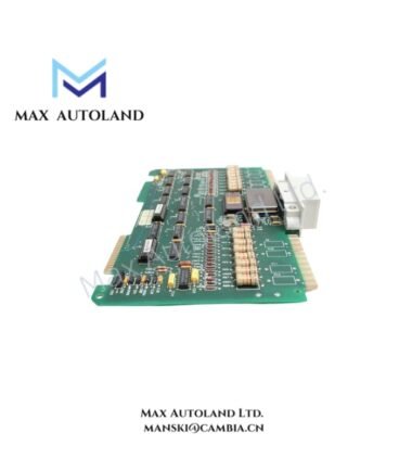
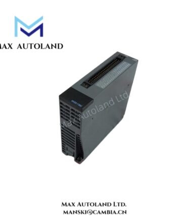
The Honeywell 620-1633, also cataloged as the Honeywell 620-1633C Processor Module, operates as a dedicated hardware component for central logic processing and data execution within IPC 620 system platforms.
Hardware Specifications
| Parameter | Specification |
|---|---|
| Model | 620-1633 |
| Spare Model | 620-1633C |
| Brand | Honeywell |
| Origin | United States |
| Weight | 0.9 kg |
| Dimensions | 7.6 cm x 26.7 cm x 16.5 cm |
| Operating Temp | 0 to 60 degC |
| Power Consumption | 5 VDC via backplane |
| Memory Capacity | 8K |
| I/O Capacity | 1024 I/O |
Channel-to-Channel Isolation and Loop Performance
This module integrates within the Honeywell process environment, adhering to specific circuit separation requirements to prevent electrical cross-talk across control networks. The architecture enforces galvanic channel-to-channel isolation limits to safeguard the internal 8K memory registers from field-side electrical transients. When interfacing with 4-20 mA HART loop protocols and distributed control system (DCS) instrumentation, the processing hardware maintains loop impedance limits to prevent signal degradation across the 1024 available I/O mapping points. Cold junction compensation (CJC) algorithms run directly within the firmware subsystem to stabilize thermal signal inputs before data packet transmission over the primary backplane.
Frequently Asked Questions
Q: Can the 620-1633 processor module be hot-swapped while the backplane is energized?
A: No. Removing or inserting the module while the system backplane power is active can cause electrical arcing, which may corrupt the 8K onboard memory or damage adjacent I/O communication cards. Power down the rack before servicing.
Q: How does the system handle the difference between the 620-1633 and the 620-1633C designations?
A: The 620-1633 denotes the primary functional product model, whereas the 620-1633C designates the spare part catalog identifier. Electrically and functionally, the internal logic processing capabilities and execution speeds remain identical.
Field Installation Guidelines
- Chassis Grounding: Ensure the rack frame connects directly to a low-impedance copper earth ground bus bar. The module relies on the chassis grounding fingers to drain high-frequency noise away from the processing circuitry.
- Wiring Separation: Route low-voltage signal wires and digital communication cables through separate conduits away from high-voltage AC power lines or inductive motor drive cables to eliminate electromagnetic interference.
- Clearance Constraints: Maintain a minimum 50 mm clearance above and below the module rack assembly to support natural thermal convection and preserve the 0 to 60 degC operating envelope.





Reviews
There are no reviews yet.