

Overview
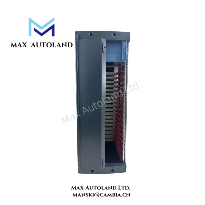
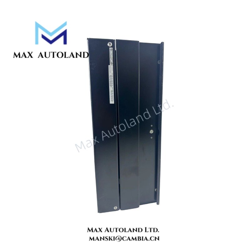
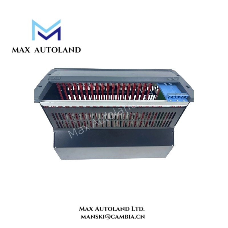
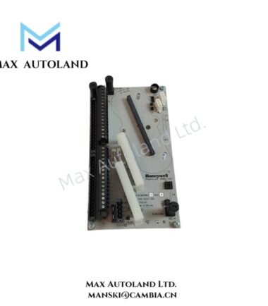
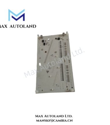
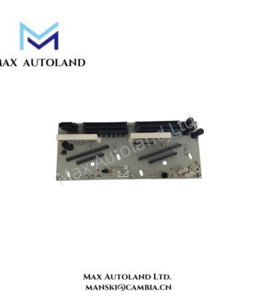
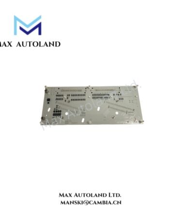
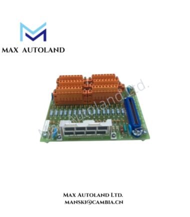
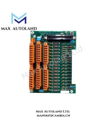
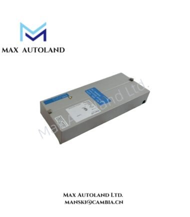
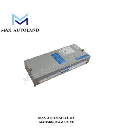
The Honeywell FS-IOCHAS-0001R, also cataloged as the IOCHAS-0001R I/O Chassis, provides the physical chassis structure for redundant I/O module pairs. It supports up to 9 pairs of redundant I/O modules and distributes the specified 5 VDC slot power through the chassis.
Hardware Specifications
| Parameter | Specification |
|---|---|
| Model | FS-IOCHAS-0001R |
| Base Model | IOCHAS-0001R |
| Brand | Honeywell |
| Product Type | I/O Chassis for Redundant Module |
| Origin | USA |
| Weight | 7.6 kg |
| Dimensions | 48.2 x 30 x 22 cm estimated shipping size |
| Operating Temp | -40 deg C to +70 deg C |
| Storage Temp | -50 deg C to +85 deg C |
| Humidity | 5-95% RH, condensing |
| Vibration | 5 g @ 10-500 Hz, IEC 60068-2-6 |
| Input Voltage | 24 VDC (18-36 V) |
| 5V-1 Slot Supply | 35 mA, IO-0001 slot 20 |
| 5V-2 Slot Supply | 35 mA, IO-0001 slot 21 |
| Redundant I/O Capacity | Up to 9 pairs |
| Approvals | CE, UL, CSA, TUV, FM |
| Tariff Code | 8537101190 |
DCS I/O Chassis Power and Module Configuration
The FS-IOCHAS-0001R provides the physical mounting and electrical interface for redundant I/O module pairs. The chassis supports up to 9 redundant pairs, while the specified 5V-1 and 5V-2 supplies provide 35 mA at the respective IO-0001 slot positions.
The chassis accepts a 24 VDC input within the specified 18-36 VDC range. Therefore, field wiring should maintain the supply within this range at the chassis input terminals. The available 5 VDC slot supply information applies specifically to IO-0001 slot 20 and slot 21.
Frequently Asked Questions
Q: How many redundant I/O module pairs can the FS-IOCHAS-0001R accommodate?
A: The IOCHAS-0001R chassis supports up to 9 pairs of redundant I/O modules.
Q: What input voltage does the FS-IOCHAS-0001R require?
A: The chassis uses a 24 VDC input with a specified operating range of 18-36 VDC.
Q: What are the specified 5 VDC slot supply values?
A: The specified 5V-1 supply is 35 mA for IO-0001 slot 20, while 5V-2 is 35 mA for IO-0001 slot 21.
Field Installation Guidelines
Install the chassis on a mechanically stable mounting surface with sufficient clearance for module insertion, removal, and cable routing. Verify that the 24 VDC supply remains within the specified 18-36 VDC range before connecting the chassis.
Route power and I/O wiring separately where practical to reduce electrical coupling. Maintain secure terminal connections and provide appropriate protective earthing according to the cabinet design and applicable installation standards.
Before installing redundant I/O modules, verify the module positions against the approved system configuration. Check that each module seats fully in its assigned chassis position and that connectors remain free from contamination or mechanical stress.
The specified operating environment is -40 deg C to +70 deg C with 5-95% RH condensing humidity. Confirm that the installation location remains within these limits. Also verify that cabinet mounting and transport provisions account for the specified 5 g vibration condition over 10-500 Hz.
Reviews
There are no reviews yet.