
Overview
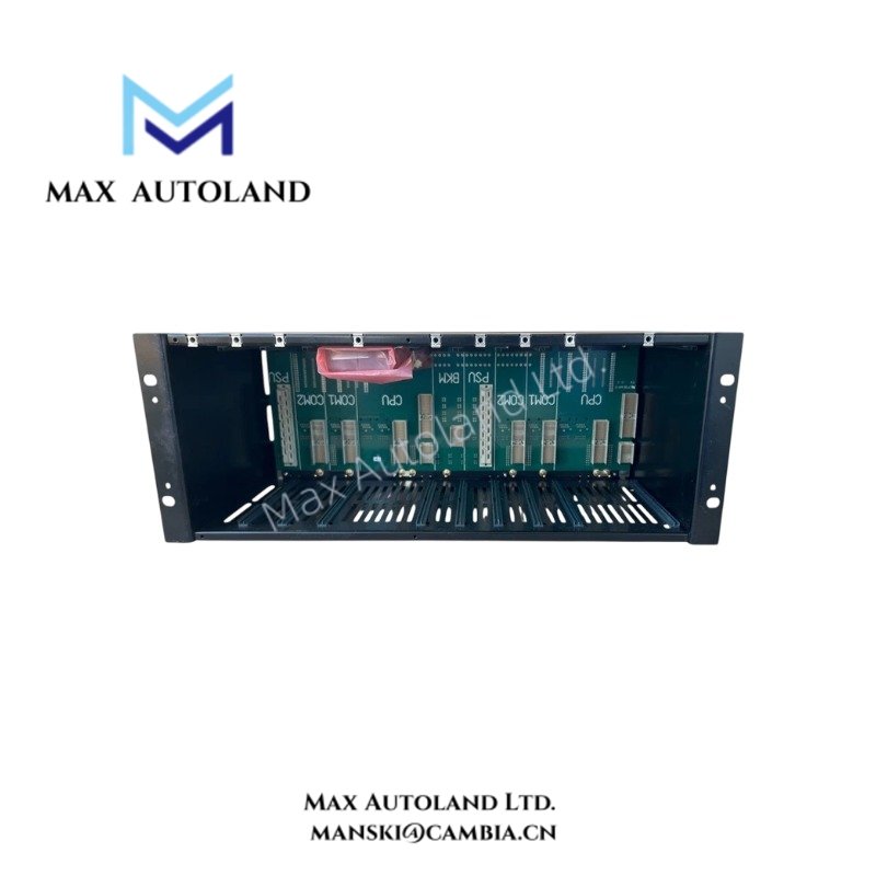
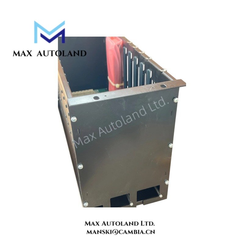
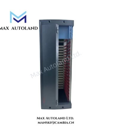
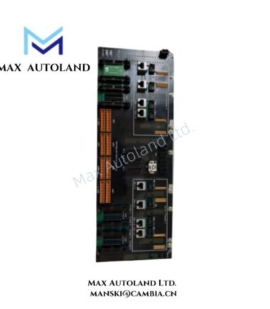
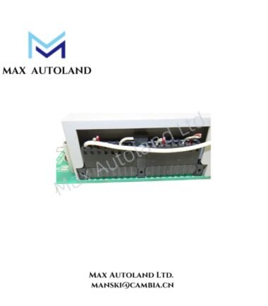
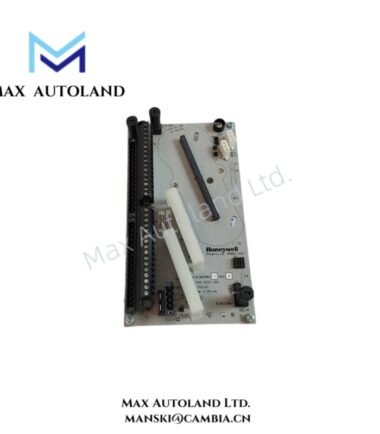
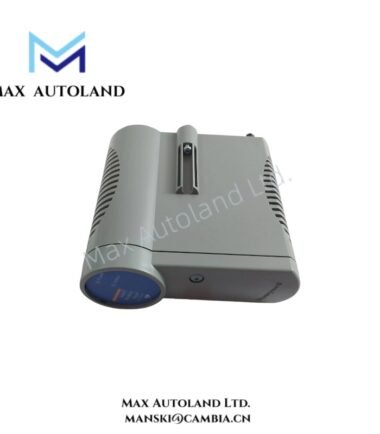
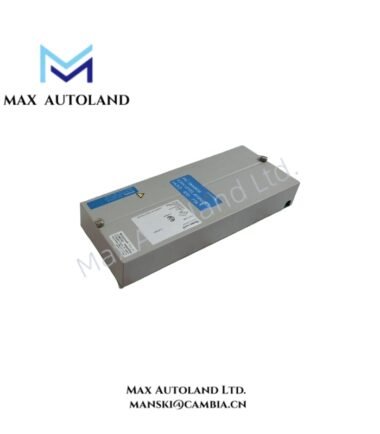
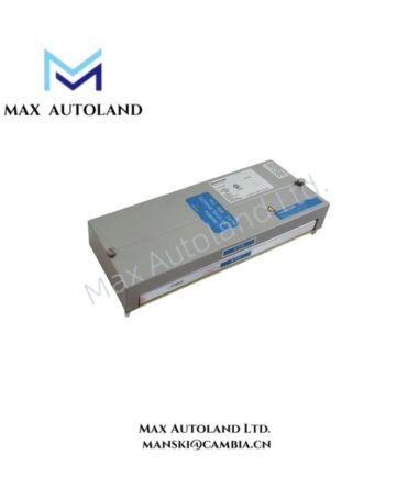
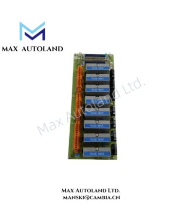
Configured for Control Processor module installation and backplane interconnection in the Honeywell Safety Manager SIS, the Honeywell FC-CPCHAS-0001 (FC-CPCHAS Controller Chassis) provides the mechanical mounting structure, internal power rails, and controller backplane interface for redundant or non-redundant controller configurations.
Hardware Specifications
| Parameter | Specification |
|---|---|
| Model | FC-CPCHAS-0001 |
| Brand | Honeywell |
| Product Type | Controller Chassis |
| Series | Safety Manager |
| Origin | USA |
| Weight | 4.9 kg |
| Dimensions | 48.3 x 28 x 17.7 cm estimated shipping size |
| Housing Standard | 19-inch rack-mountable |
| Supply Voltage | 24 VDC |
| Power Consumption | +5V-1: 0.05 A; +5V-2: 0.05 A |
| Operating Temp | -5 deg C to +70 deg C |
| Storage Temp | -25 deg C to +80 deg C |
| Relative Humidity | 5% to 95% RH, non-condensing |
| Approvals | CE, UL, CSA, TUV, FM |
| Configuration | Redundant and non-redundant controller configurations |
Safety Manager Controller Backplane and Power Interface
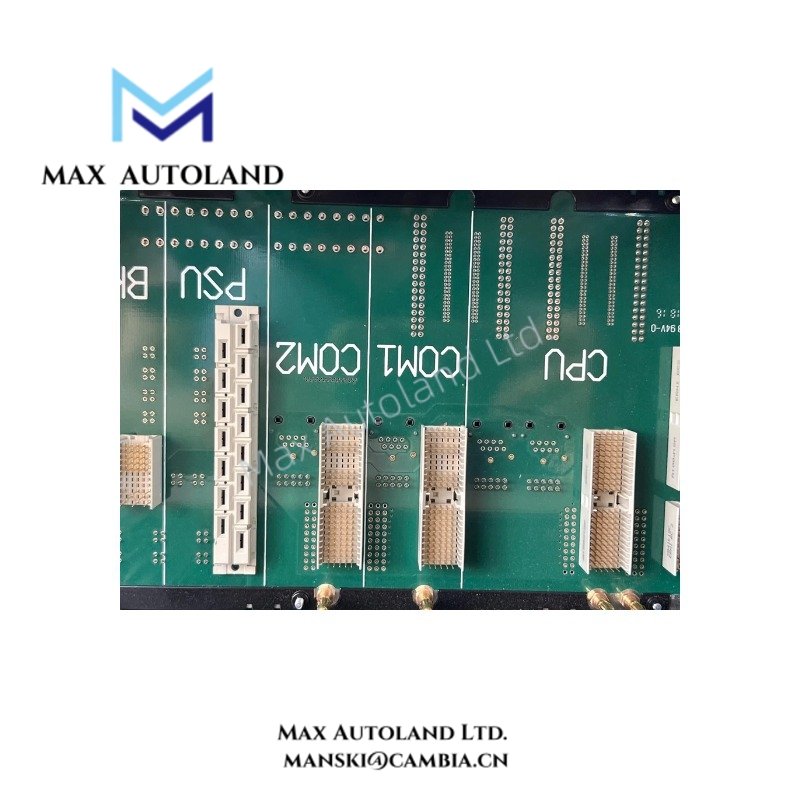
The FC-CPCHAS-0001 provides the physical mounting and electrical interface for Control Processor modules. Its controller backplane distributes the internal power rails and establishes the module-to-chassis electrical connections.
The chassis typically mounts at the upper section of a Safety Manager cabinet, while I/O chassis occupy the lower cabinet positions. This arrangement separates controller processing hardware from I/O termination and field interface hardware.
The specified internal rail loads are +5V-1 at 0.05 A and +5V-2 at 0.05 A. Therefore, installation should maintain the specified controller chassis power distribution arrangement and avoid exceeding the applicable system power budget.
Frequently Asked Questions
Q: What controller configuration does the FC-CPCHAS-0001 support?
A: The chassis supports both redundant and non-redundant Control Processor configurations.
Q: What is the mounting format of the FC-CPCHAS-0001?
A: The chassis uses a 19-inch rack-mountable housing and typically installs in the controller section of a Safety Manager cabinet.
Q: What internal power rails does the chassis specify?
A: The specified internal rails are +5V-1 at 0.05 A and +5V-2 at 0.05 A.
Field Installation Guidelines
Install the FC-CPCHAS-0001 in the designated controller section of the Safety Manager cabinet and secure the chassis using the appropriate rack mounting hardware.
Before inserting Control Processor modules, verify that the chassis, backplane connectors, and module interfaces remain free from mechanical damage and contamination. Align each module with its designated slot before applying insertion force.
Route power and communication wiring separately from high-energy switching conductors where the cabinet design permits. Maintain proper protective bonding and cabinet grounding according to the applicable Safety Manager installation documentation.
Do not modify the backplane, power rails, or chassis wiring. Confirm the available 24 VDC supply and internal power distribution before energizing the controller assembly.
Reviews
There are no reviews yet.