



Overview
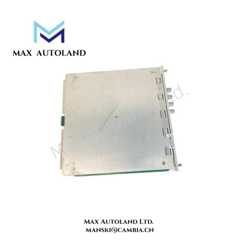
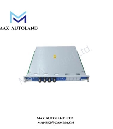
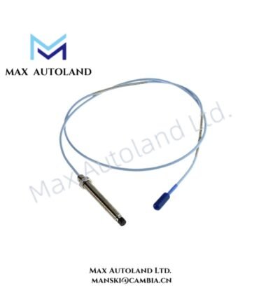
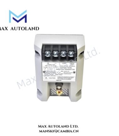
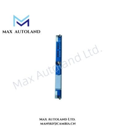
Configured for proximity signal measurement in the Bently Nevada 3500 Machinery Protection System, the Bently Nevada 3500/40-03-01 (3500/40M Proximitor Monitor) provides four-channel signal conditioning, measurement, and alarm processing for eddy-current proximity transducer inputs. The module supports radial vibration, thrust position, differential expansion, eccentricity, and REBAM measurement functions through channel-pair configuration.
Hardware Specifications
| Parameter | Specification |
|---|---|
| Model | 3500/40-03-01 |
| Base Model | 3500/40M |
| Brand | Bently Nevada |
| Product Type | 4-Channel Proximitor Monitor Module |
| System | 3500 Machinery Protection System |
| Origin | USA |
| Number of Channels | 4 channels |
| Channel Configuration | Channel-pair configurable |
| Transducer Inputs | Bently Nevada eddy-current proximity transducers |
| Input Impedance | 10 kOhm standard; 50 kOhm for TMR parallel configuration |
| Transducer Power Supply | -24 VDC |
| Radial / Thrust / Eccentricity Sensitivity | 3.94 mV/um (100 mV/mil) or 7.87 mV/um (200 mV/mil) |
| Differential Expansion Sensitivity | 0.394 mV/um (10 mV/mil) or 0.787 mV/um (20 mV/mil) |
| Measurement Accuracy | Typically within +/- 0.33% of full scale; +/- 1% maximum for most measurements |
| Alarm Setpoints | 0% to 100% of full-scale range |
| Alarm Setpoint Accuracy | Within 0.13% of desired value |
| Alert Time Delay | 1 s to 60 s |
| Danger Time Delay | 0.1 s or 1 s to 60 s |
| Buffered Output Impedance | 550 Ohm |
| Buffered Outputs | Short-circuit protected, unbuffered raw transducer signals |
| Power Consumption | 7 W typical |
| Operating Temp | 0 deg C to +65 deg C |
| Dimensions | Standard 3500 rack module format |
| Weight | Approximately 0.91 kg |
| Certifications / Compliance | CE, UL, ATEX, CSA, EMC Directive |
Eddy-Current Signal Processing and Rotor Dynamics
The 3500/40M processes proximity probe signals using defined eddy-current scaling characteristics. Therefore, technicians must match the monitor configuration with the installed probe system and measurement range.
For radial vibration, thrust position, and eccentricity measurements, the module supports 100 mV/mil and 200 mV/mil scaling equivalents. Differential expansion uses lower sensitivity ranges of 10 mV/mil or 20 mV/mil.
During commissioning, technicians should validate probe gap voltage against the applicable Bently Nevada transducer installation requirements. A nominal -10 VDC gap target is commonly used for compatible proximity probe systems, but the actual acceptance value must follow the installed probe and monitor documentation.
The module compares measured values with programmable Alert and Danger thresholds. Consequently, alarm processing can provide hardware-level machinery protection while diagnostic systems receive measurement data through the 3500 system interface.
Frequently Asked Questions (FAQ)
Q: Can the 3500/40-03-01 perform different measurement functions on all four channels independently?
A: The module configures channels in pairs. Each channel pair can support a selected monitoring function such as radial vibration, thrust position, differential expansion, eccentricity, or REBAM.
Q: What transducer signal does the module accept?
A: The module accepts signals from compatible Bently Nevada eddy-current proximity transducers and provides the required -24 VDC transducer supply.
Q: Can technicians remove the module while the rack remains energized?
A: The supplied information identifies the module as hot-swappable. Installation and removal must still follow the applicable 3500 rack procedures and site electrical safety requirements.
Field Installation Guidelines
- Install the module in the designated 3500 rack slot and verify mechanical engagement with the rack backplane.
- Confirm that the installed proximity probes, extension cables, and monitor configuration use compatible electrical scaling.
- Route probe signal cables separately from high-voltage power conductors and high-current switching circuits where practical.
- Maintain cable shielding and grounding according to the Bently Nevada installation documentation and the plant grounding scheme.
- Verify probe polarity, channel assignment, and transducer connections before applying operating power.
- Check the probe gap voltage during commissioning and compare the measured value with the applicable probe system requirements.
- Confirm Alert and Danger thresholds before placing the machinery protection function into service.
- Verify buffered output connections before attaching external diagnostic equipment.
- Apply rack configuration software settings only after confirming the installed transducer type and required measurement function.
- Perform functional alarm checks after installation and record the resulting channel status and alarm behavior.


Reviews
There are no reviews yet.