

Overview
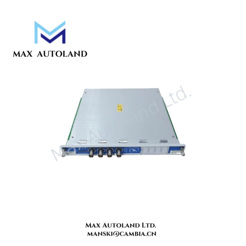
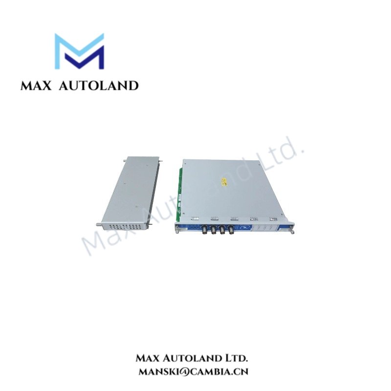
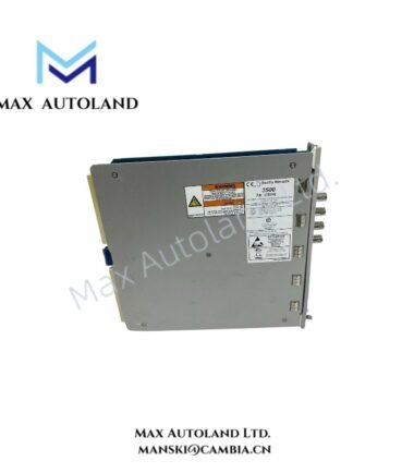
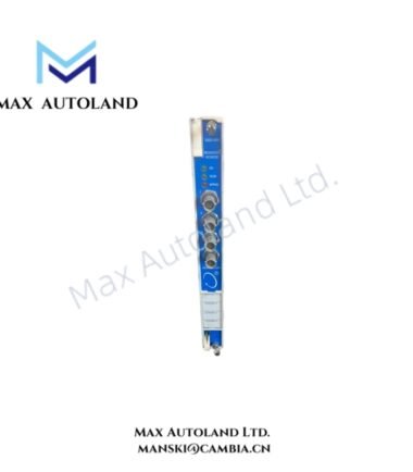
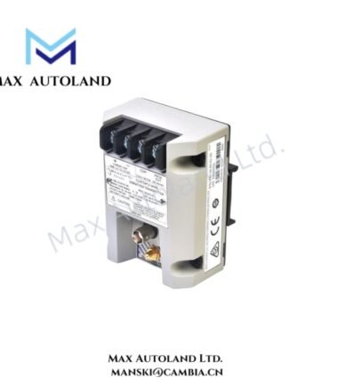
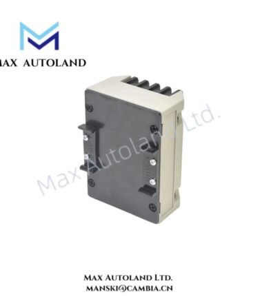
The Bently Nevada 3500/40-02-01, also cataloged as the 3500/40M Proximitor Monitor Module, processes eddy-current proximity transducer signals within the 3500 Machinery Protection System. It converts conditioned probe signals into vibration and position measurements, then evaluates those measurements against configured Alert and Danger thresholds.
Hardware Specifications
| Parameter | Specification |
|---|---|
| Model | Bently Nevada 3500/40-02-01 |
| Base Model | 3500/40M |
| Brand | Bently Nevada |
| Series | 3500 Series |
| Product Type | 4-Channel Proximitor Monitor Module |
| Origin | Not specified in the supplied data |
| Number of Channels | 4 |
| Measurement Functions | Radial vibration, thrust position, differential expansion, eccentricity, REBAM |
| Transducer Type | Bently Nevada eddy-current proximity transducers |
| Transducer Power Supply | -24 VDC excitation output |
| Input Impedance | 10 kOhm, standard I/O |
| Power Consumption | 7.0 to 7.7 W typical |
| Direct Filter | Programmable 4 Hz to 4000 Hz or 1 Hz to 600 Hz |
| Gap Filter | -3 dB at 0.09 Hz |
| Not 1X and Vector Filters | Configurable for speed tracking |
| Buffered Outputs | One front-panel coaxial connector per channel |
| Buffered Output Impedance | Approximately 550 Ohm |
| Buffered Output Protection | Short-circuit protected |
| Operating Temperature | -30 deg C to +65 deg C |
| Storage Temperature | -40 deg C to +85 deg C |
| Relative Humidity | Up to 95%, non-condensing |
| Dimensions | Approximately 241.3 mm x 24.4 mm x 241.8 mm |
| Weight | Approximately 0.91 kg |
| Front Panel Indicators | OK, TX/RX, Bypass |
| Configuration | 3500 Rack Configuration Software |
| System Integration | TDI 3500/22M and System 1 platform |
Eddy-Current Probe Signal Processing
The 3500/40M accepts signals from Bently Nevada eddy-current proximity transducers and processes the resulting displacement signals. Each channel pair can support configured measurements including radial vibration, thrust position, differential expansion, eccentricity, and REBAM.
The input circuit provides -24 VDC transducer excitation and uses a 10 kOhm standard I/O input impedance. Therefore, installation should maintain the specified probe, extension cable, and monitor signal path configuration.
The module also provides programmable filtering. Users can select direct filter ranges of 4 Hz to 4000 Hz or 1 Hz to 600 Hz, while the gap filter provides a -3 dB point at 0.09 Hz. Not 1X and vector filtering supports speed-related measurement processing.
The front-panel buffered outputs provide direct access to each channel signal. These outputs use coaxial connectors, provide approximately 550 Ohm output impedance, and include short-circuit protection.
Frequently Asked Questions (FAQ)
Q: How many proximity transducer channels does the 3500/40M provide?
A: The module provides four independent monitoring channels for compatible Bently Nevada eddy-current proximity transducer inputs.
Q: Which measurements can the 3500/40M perform?
A: The configured channels can measure radial vibration, thrust position, differential expansion, eccentricity, and REBAM.
Q: What filtering options are available?
A: The module provides programmable direct filters, a gap filter, and configurable Not 1X and vector filters for speed tracking.
Field Installation Guidelines
- Install the module in the designated 3500 Series rack slot and follow the rack wiring arrangement.
- Verify that the installed I/O configuration matches the selected monitor and transducer circuit.
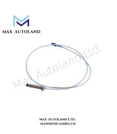
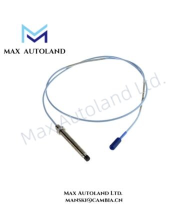
- Use compatible Bently Nevada proximity probes and extension cables for the measurement loop.
- Route probe signal cables separately from high-current power conductors where practical to reduce electrical interference.
- Maintain cable shielding and termination practices specified for the 3500 rack installation.
- Verify probe polarity, excitation connections, and signal continuity before applying operating power.
- Check the probe gap voltage during commissioning and confirm that the measured value corresponds with the applicable transducer installation requirements.
- Confirm channel configuration and measurement assignments through the 3500 Rack Configuration Software.
- Verify OK, TX/RX, and Bypass indicators after installation.
- Confirm Alert and Danger settings before placing the machinery protection channel into service.
- Do not modify field wiring while the associated circuit remains energized unless the site procedure specifically permits the operation.


Reviews
There are no reviews yet.