
Overview
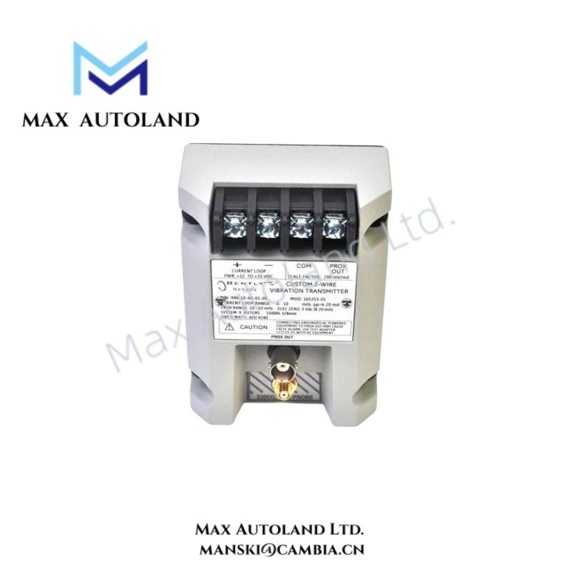
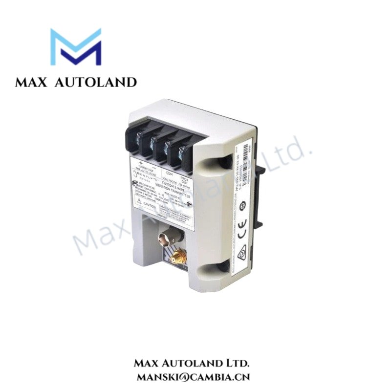
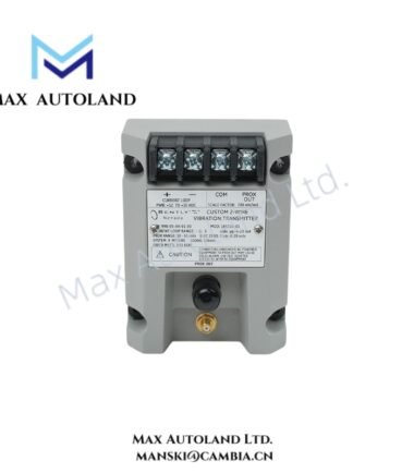
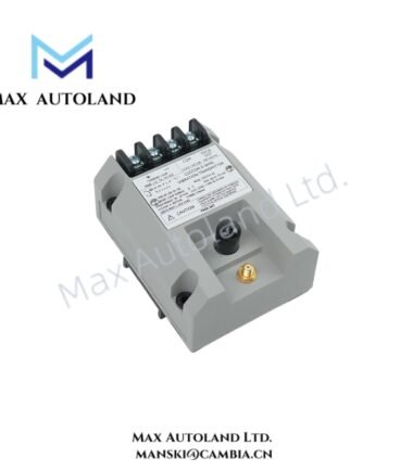
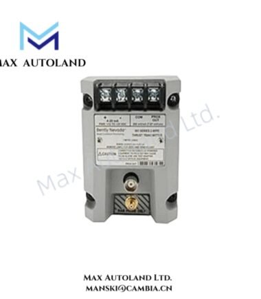
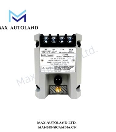
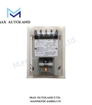
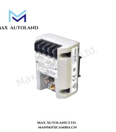
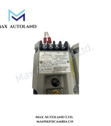
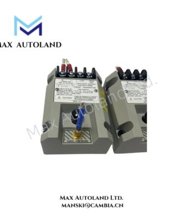
Configured for axial shaft position measurement in a 3300 NSv proximity probe loop, the Bently Nevada 991-50-XX-01-00 (991 Thrust Transmitter) provides direct signal conditioning and 4-20 mA transmission for machinery monitoring circuits.
Hardware Specifications
| Parameter | Specification |
|---|---|
| Model | 991-50-XX-01-00 |
| Brand | Bently Nevada |
| Product Type | Two-Wire Thrust Transmitter |
| Model Series | 991 Series |
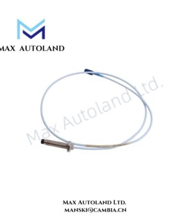
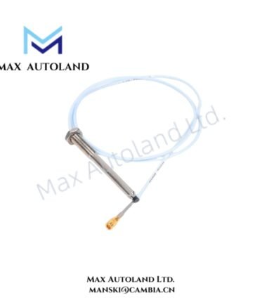
| Input | One 3300 NSv proximity probe with matching extension cable |
| System Length | 5.0 m (16.4 ft) total system length |
| Output | 4-20 mA DC, proportional to axial shaft position |
| Power Supply | +12 to +35 VDC, loop-powered |
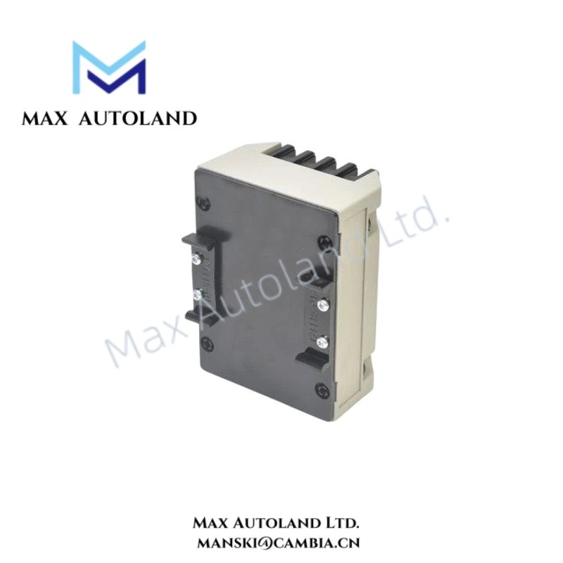
| Mounting | 35 mm DIN rail clips |
| Agency Approval | Standard / not required |
| Loop Accuracy | Within +/- 1.5% of specified full-scale range, typical |
| Dynamic Output | PROX OUT and COM terminals plus coaxial connector |
| Special Circuits | Power-up inhibit and Not OK / Signal Defeat |
| Enclosure | Potted construction |
| Operating Humidity | Up to 100% condensing |
| Origin | USA |
| Power Consumption | Loop-powered; supply requirement +12 to +35 VDC |
Eddy-Current Probe Scaling and Gap Voltage
The 991 transmitter interfaces directly with a 3300 NSv eddy-current proximity probe system. The probe detects axial shaft displacement, while the transmitter conditions the probe signal and produces a proportional 4-20 mA output.
The 5.0 m system-length option matches the specified probe and extension-cable configuration. During commissioning, technicians should verify the probe gap voltage against the applicable Bently Nevada installation requirements before placing the loop into service.
The transmitter also provides PROX OUT and COM connections for diagnostic access to probe-related signals. Therefore, technicians can inspect the measurement circuit without changing the primary 4-20 mA signal path.
The power-up inhibit circuit suppresses startup transients. In addition, the Not OK / Signal Defeat circuit prevents invalid probe conditions from generating unintended machinery protection responses.
Frequently Asked Questions (FAQ)
Q: What probe does the 991-50-XX-01-00 accept?
A: The transmitter accepts one 3300 NSv non-contacting proximity probe with the matching extension cable.
Q: What electrical output does the transmitter provide?
A: It provides a loop-powered 4-20 mA DC output proportional to measured axial shaft position.
Q: Can technicians access the probe signal for diagnostics?
A: Yes. The transmitter provides PROX OUT and COM terminals plus a coaxial connector for dynamic diagnostic signals.
Field Installation Guidelines
- Mount the transmitter using the specified 35 mm DIN rail clips and maintain adequate clearance for wiring access.
- Connect the 3300 NSv probe and matching extension cable according to the applicable Bently Nevada wiring documentation.
- Route probe wiring separately from high-current power conductors and switching circuits to reduce electrical interference.
- Maintain correct polarity throughout the 4-20 mA loop and verify the available loop supply remains within +12 to +35 VDC.
- Connect cable shields according to the site grounding scheme and avoid creating unintended ground loops.
- Verify probe gap voltage before commissioning the axial-position measurement loop.
- Check the 4-20 mA output against the expected shaft-position condition before enabling alarms or machinery protection logic.
- Use the PROX OUT and COM connections for diagnostic verification when investigating probe or signal-conditioning faults.
- Confirm the power-up inhibit and Not OK / Signal Defeat functions during commissioning where the transmitter feeds protection or alarm logic.


Reviews
There are no reviews yet.