


Overview
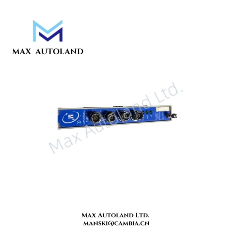
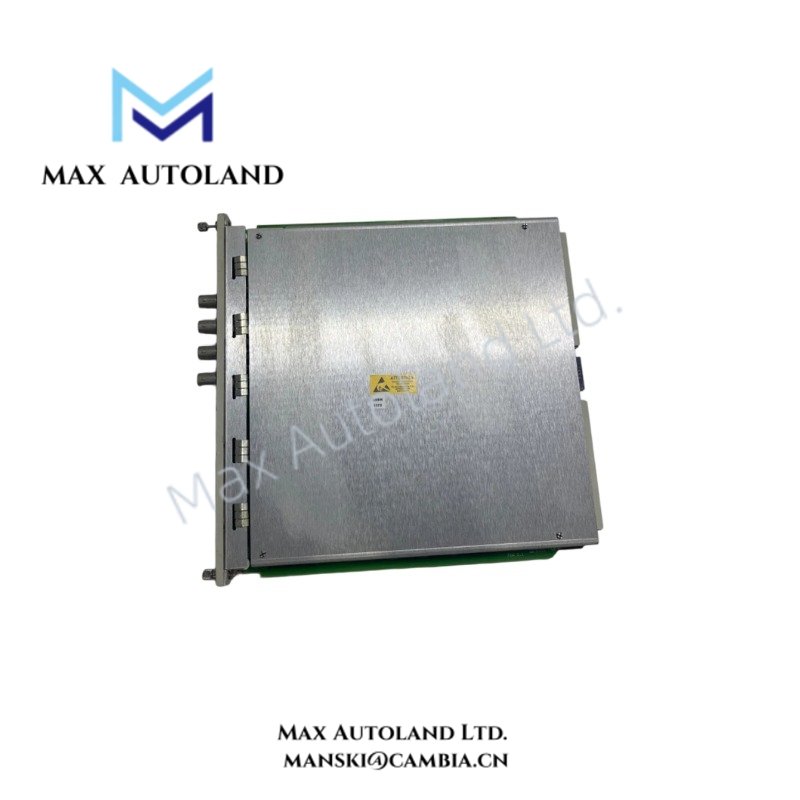
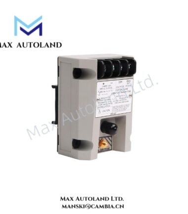
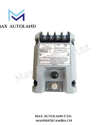
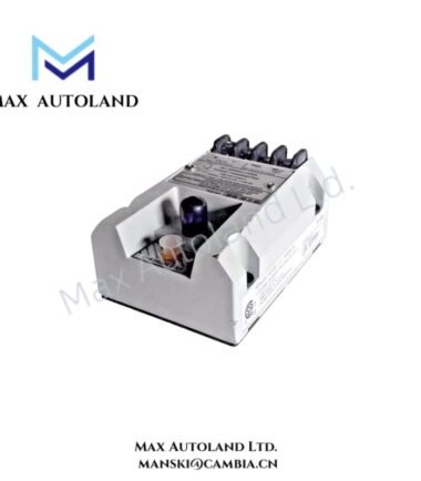
Configured for proximity and seismic signal monitoring in the 3500 Machinery Protection System, the Bently Nevada 3500/42 (125972-02) (3500/42 Proximitor/Seismic Monitor) conditions four transducer inputs and compares measured vibration or position values with programmable alarm setpoints.
Hardware Specifications
| Parameter | Specification |
|---|---|
| Model | 3500/42 |
| Part Number | 125972-02 |
| Brand | Bently Nevada |
| Product Type | 4-Channel Proximitor/Seismic Monitor |
| Origin | USA |
| Number of Channels | 4 |
| Supported Inputs | Proximity, velocity, and acceleration transducers |
| Input Impedance | 10 kOhm for proximity/acceleration inputs |
| Supported Measurements | Radial vibration, thrust position, differential expansion, acceleration, velocity, REBAM |
| Buffered Outputs | Short-circuit protected; 550 Ohm source impedance |
| Recorder Outputs | 4-20 mA proportional to measured value |
| Recorder Output Accuracy | +/- 0.25% at room temperature |
| Frequency Response – Radial Vibration | 4 Hz to 4 kHz, direct filter |
| Frequency Response – Thrust/Expansion | 1.2 Hz, direct filter |
| Frequency Response – Acceleration/Velocity | 10 Hz to 30 kHz, unfiltered |
| Measurement Accuracy | +/- 0.33% typical; +/- 1% maximum for most parameters |
| Alarm Setpoint Range | 0% to 100% of full-scale range |
| Alarm Setpoint Accuracy | +/- 0.13% |
| Alert Delay | Programmable from 1 s to 60 s |
| Danger Delay | Programmable from 0.1 s to 60 s |
| Operating Temp | -30 deg C to +65 deg C |
| Certifications | ATEX, cNRTLus, CE; EN 61010-1 and EMC compliance |
| Dimensions | 241.3 x 24.4 x 241.8 mm |
| Weight | Approx. 0.91 kg |
| Power Consumption | Not specified in the supplied data |
Eddy-Current Signal and Rotor Dynamics
The 3500/42 accepts proximity transducer signals for rotating machinery vibration and position measurements. The monitor conditions the incoming signals before applying measurement processing and alarm logic.
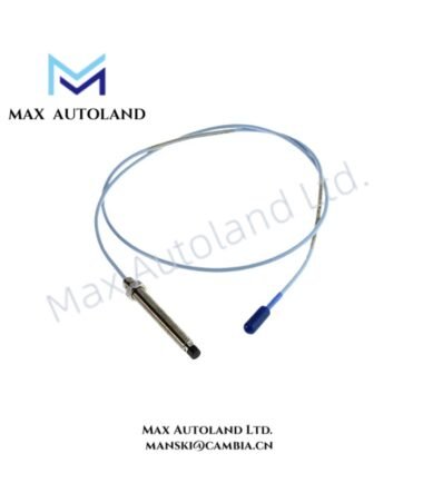
For eddy-current probe installations, technicians should verify the probe gap voltage against the specified transducer system requirements before commissioning. A nominal -10 VDC target commonly applies to Bently Nevada proximity probe gap validation, but the actual target must follow the installed probe and transducer configuration.
The four-channel architecture permits simultaneous monitoring of selected radial vibration, thrust position, differential expansion, acceleration, or velocity parameters. Therefore, correct channel configuration and transducer scaling directly affect the resulting measurement values and alarm thresholds.
The buffered outputs use a 550 Ohm source impedance and provide short-circuit protection. In addition, the recorder outputs provide 4-20 mA signals proportional to the measured variables for external monitoring or recording equipment.
Frequently Asked Questions (FAQ)
Q: How many transducer channels does the 3500/42 provide?
A: The 3500/42 provides four independent monitoring channels for supported proximity, velocity, or acceleration transducer inputs.
Q: What alarm delay ranges can the module provide?
A: The Alert delay is programmable from 1 s to 60 s, while the Danger delay is programmable from 0.1 s to 60 s.
Q: Does the supplied data specify the module power consumption?
A: No. The supplied technical data does not provide a specific power consumption value. The applicable 3500 system documentation should be used for installation power requirements.
Field Installation Guidelines
- Install the module in the designated 3500 Machinery Protection System rack position.
- Verify the module part number and rack configuration before energizing the system.
- Confirm each transducer connection against the configured channel assignment.
- Route transducer wiring separately from high-voltage power conductors and high-current switching circuits.
- Maintain appropriate cable shielding and grounding practices according to the installed Bently Nevada transducer system.
- Verify eddy-current probe gap voltage before enabling vibration or position alarm functions.
- Confirm the configured measurement range and transducer scaling before accepting process measurements.
- Check buffered output wiring for the specified source impedance and connected equipment requirements.
- Verify 4-20 mA recorder output polarity and loop termination before connecting external recording equipment.
- Confirm Alert and Danger setpoints and their associated time delays during commissioning.
- Do not bypass or modify protection functions without following the applicable machinery protection system procedure.
- Maintain the specified operating environment of -30 deg C to +65 deg C.




Reviews
There are no reviews yet.