
Overview
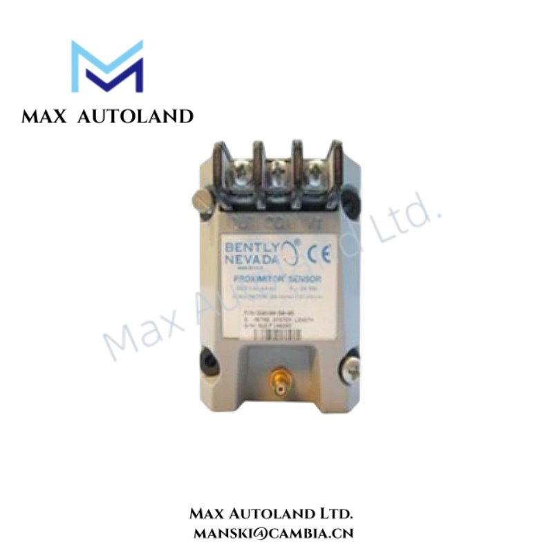
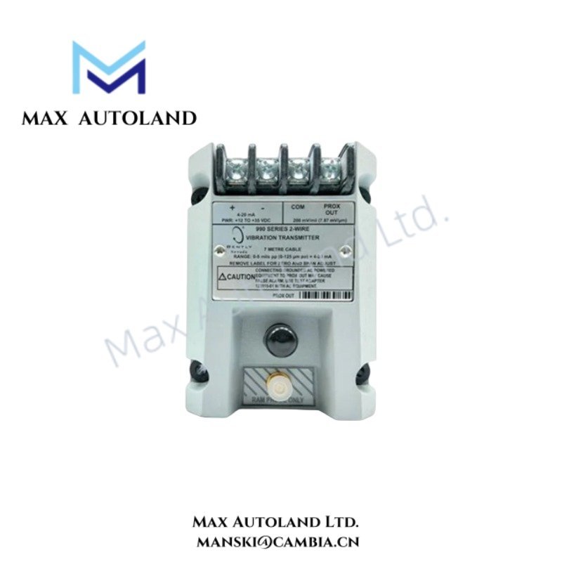
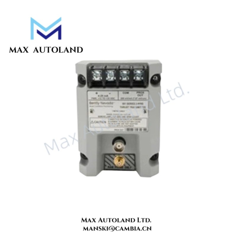
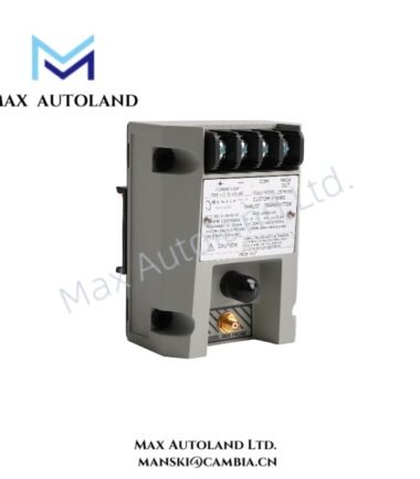
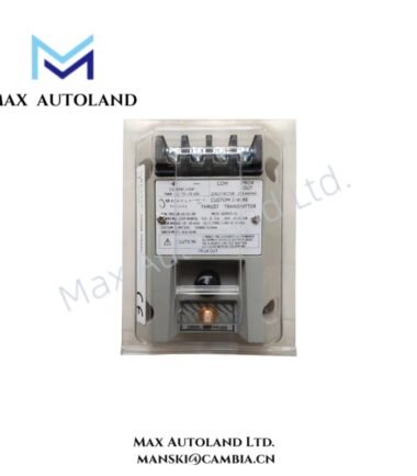
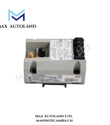
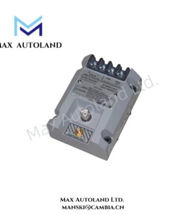
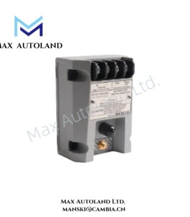
Configured for thrust position measurement with a non-contacting 3300 NSv proximity probe, the Bently Nevada 991-25-XX-01-CN (991 Thrust Transmitter) converts probe displacement into a proportional current-loop output. The transmitter accepts +12 to +35 VDC at its terminals and supports external non-interacting zero and span adjustments.
Hardware Specifications
| Parameter | Specification |
|---|---|
| Model | 991-25-XX-01-CN |
| Brand | Bently Nevada |
| Product Type | 991 Thrust Transmitter |
| Origin | USA |
| Shipment Location | Xiamen, China |
| Weight | 0.44 kg |
| Dimensions | 7.3 x 5 x 10 cm |
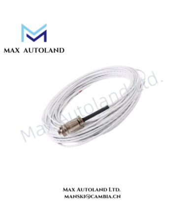
| Input | 1 non-contacting 3300 NSv Proximity Probe and extension cable |
| Power Supply | +12 to +35 VDC at transmitter terminal |
| Maximum Loop Resistance | 1,000 ohm including cable at 35 VDC |
| Current Limiting | 23 mA typical |
| Zero and Span | Non-interacting external adjustments |
| Measurement Range | 25-0-25 mils |
| Extension Cable Length | 5.0 m (16.4 ft) |
| Mounting | 35 mm DIN rail clips |
| Tariff Code | 8537101190 |
Bently Nevada Mechanical Measurement Characteristics
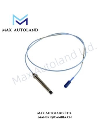
The 991 transmitter interfaces directly with a 3300 NSv non-contacting proximity probe and its extension cable. The probe senses shaft or thrust movement through an eddy-current measurement principle, while the transmitter scales the probe signal for current-loop transmission.
The specified 25-0-25 mil measurement configuration provides a total span of 50 mils around the reference position. Therefore, correct probe installation and gap-voltage validation directly affect the resulting thrust measurement.
The transmitter requires +12 to +35 VDC at the transmitter terminal. Moreover, the loop resistance must remain within 1,000 ohm, including cable resistance, when operating from a 35 VDC supply. The 23 mA typical current-limiting value defines the transmitter’s output protection behavior.
Frequently Asked Questions (FAQ)
Q: Which proximity probe does the 991-25-XX-01-CN accept?
A: It accepts one non-contacting 3300 NSv Proximity Probe together with its extension cable.
Q: What supply voltage does the transmitter require?
A: The transmitter requires +12 to +35 VDC at the transmitter terminal.
Q: Can technicians adjust zero and span independently?
A: Yes. The transmitter provides external, non-interacting zero and span adjustments.
Field Installation Guidelines
- Mount the transmitter using the specified 35 mm DIN-rail clips.
- Connect only the specified 3300 NSv proximity probe and compatible extension cable.
- Verify +12 to +35 VDC at the transmitter terminals before commissioning.
- Keep the total loop resistance within 1,000 ohm when operating from a 35 VDC supply.
- Route probe and extension-cable wiring separately from high-current switching and power conductors where practical.
- Maintain appropriate cable shielding and grounding practices to reduce electrical interference.
- Verify probe mechanical installation and measurement gap before applying the operating signal.
- Confirm zero and span settings after the mechanical installation reaches its normal operating condition.




Reviews
There are no reviews yet.