
Overview
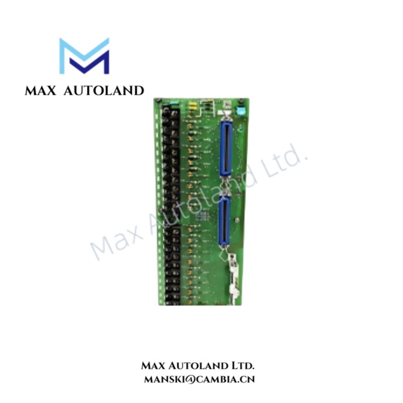
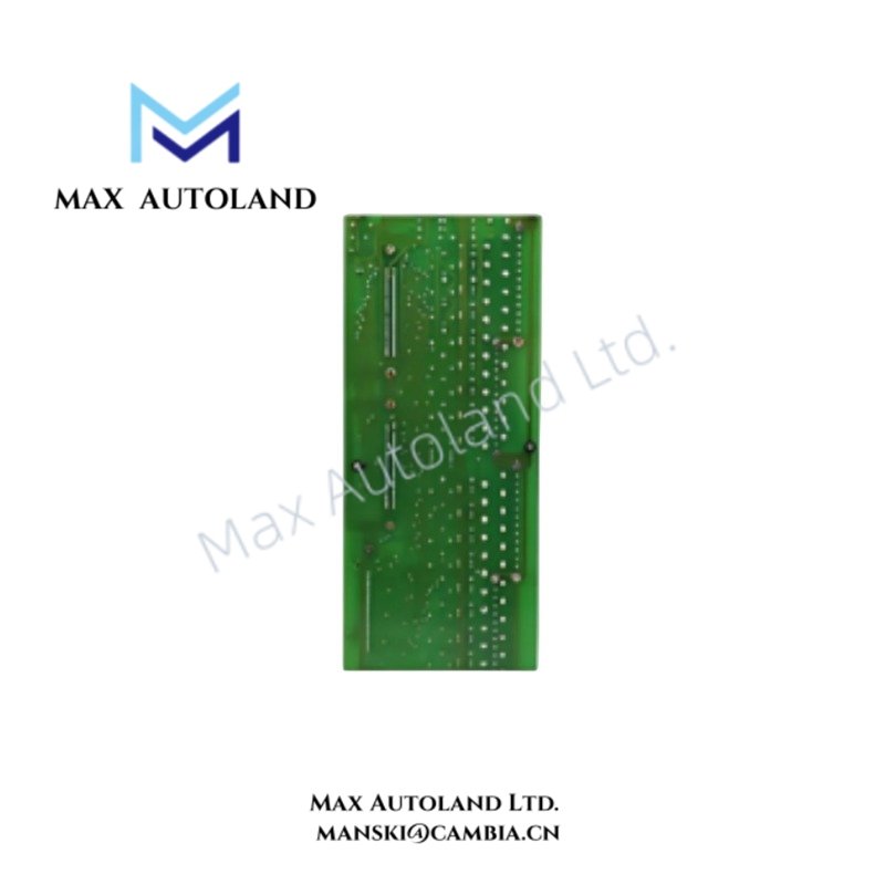
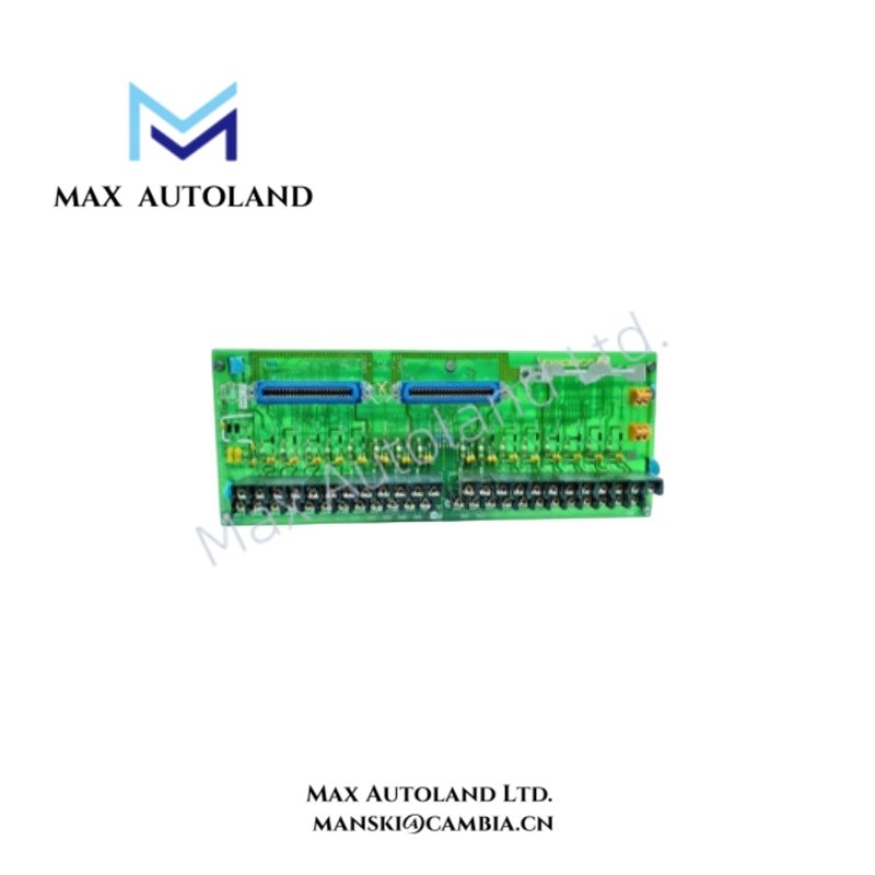
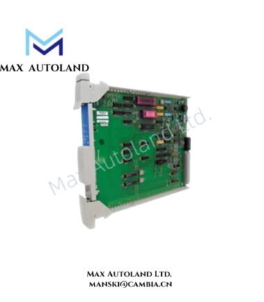
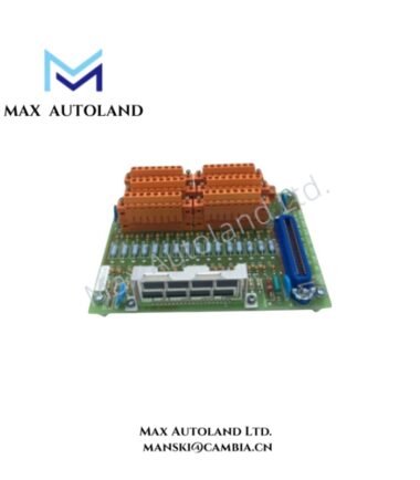
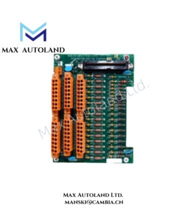
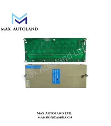
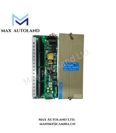
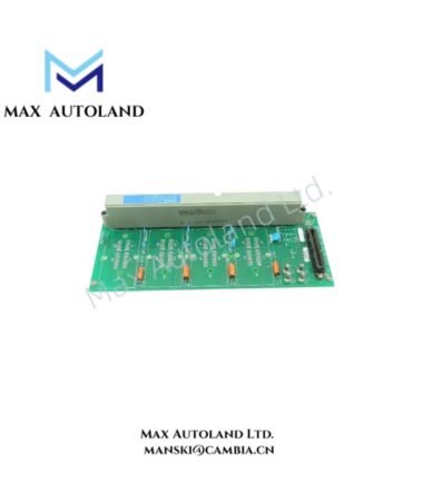
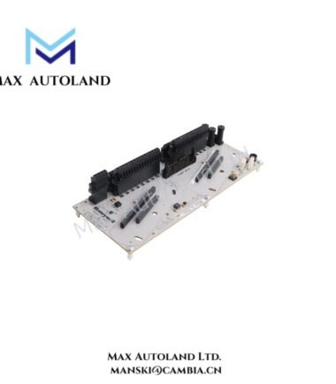
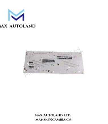
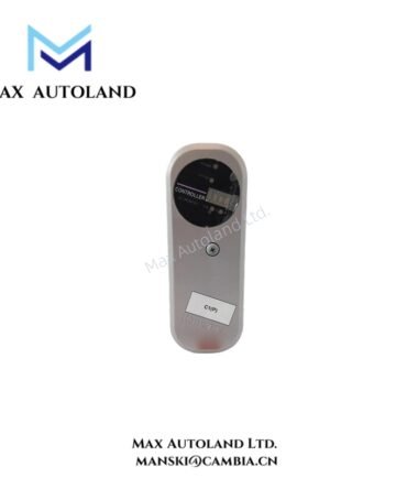
Configured for 16-channel 4-20 mA signal termination in Honeywell process control systems, the Honeywell MU-GAIH14 (MU-GAIH14 Analog Input Field Termination Assembly) provides field signal conditioning, isolation, and loop interface functions. It accepts 4-20 mA transmitter signals and provides conditioned 1-5 VDC outputs for high-level analog input processing.
Hardware Specifications
| Parameter | Specification |
|---|---|
| Model | MU-GAIH14 |
| Brand | Honeywell |
| Product Type | Analog Input Field Termination Assembly |
| Input Channels | 16 |
| Input Signal | 4-20 mA analog input |
| Output Signal | 1-5 VDC |
| Field Transmitter Support | 2-wire and 3-wire transmitters |
| HART Support | HART digital communication pass-through |
| Isolation | Galvanic isolation |
| Power Supply | 24 VDC |
| Power Consumption | Approx. 1.2 A |
| Terminal Type | C-style screw terminal |
| Mounting | B-standard rack mount / DIN rail compatible |
| Operating Temp | -20 deg C to +60 deg C |
| Storage Temp | -40 deg C to +85 deg C |
4-20 mA HART and Channel Isolation
The MU-GAIH14 terminates up to 16 analog current loops and transfers conditioned signals toward the associated high-level analog input hardware. The assembly supports 4-20 mA process transmitters, including 2-wire and 3-wire configurations with floating DC excitation.
Galvanic isolation separates field-side signal circuits from sensitive control electronics. Therefore, the isolation path limits ground-loop effects and reduces unwanted electrical coupling between signal circuits.
The assembly also passes HART communication superimposed on the 4-20 mA loop. Consequently, compatible smart transmitters can exchange digital configuration, diagnostic, and process information without removing the analog measurement signal.
Frequently Asked Questions
Q: How many analog input channels does the MU-GAIH14 provide?
A: The MU-GAIH14 provides 16 analog input channels for 4-20 mA field signals.
Q: Does the MU-GAIH14 support HART communication?
A: Yes. The supplied specifications identify HART pass-through for compatible smart transmitters operating on 4-20 mA loops.
Q: What output does the assembly provide to the high-level analog input hardware?
A: The specified conditioned output is 1-5 VDC.
Field Installation Guidelines
- Install the assembly on the specified rack or DIN rail mounting arrangement and secure all mechanical fasteners.
- Verify that the field wiring matches the intended 2-wire or 3-wire transmitter configuration before energizing the circuit.
- Maintain separation between analog signal wiring and high-voltage or high-current conductors to reduce electrical interference.
- Route cable shields according to the control system grounding design. Avoid creating unintended shield ground loops.
- Tighten C-style screw terminals to the applicable terminal manufacturer’s recommended torque.
- Confirm 24 VDC supply polarity and wiring before applying power.
- Verify each 4-20 mA loop at commissioning and confirm the expected 1-5 VDC conditioned output.
- When HART devices are connected, verify that the loop wiring permits the required HART communication path.
- Check channel isolation and field-loop continuity before connecting the assembly to energized control electronics.
- Confirm that the installation environment remains within the specified -20 deg C to +60 deg C operating temperature range.
Reviews
There are no reviews yet.