
Overview
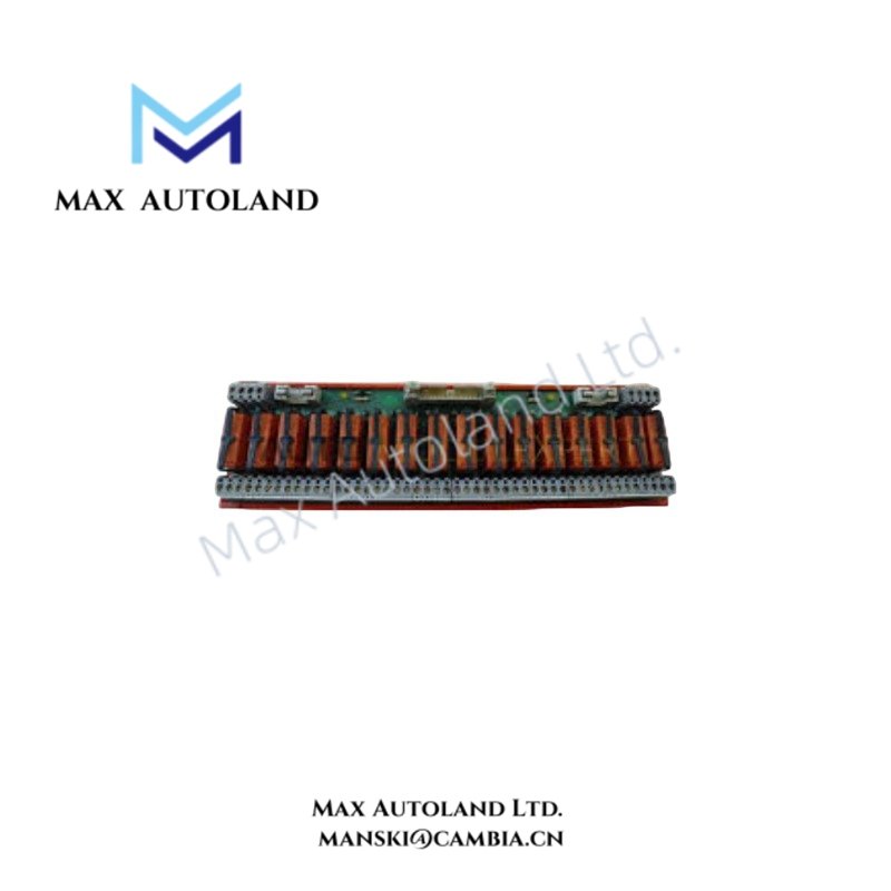
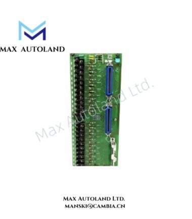
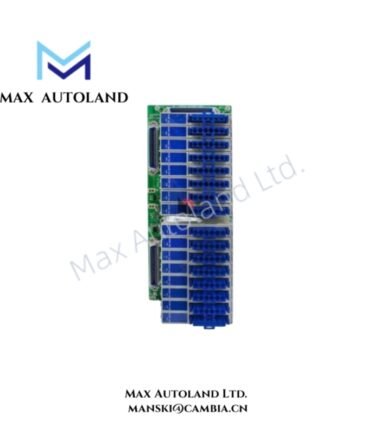
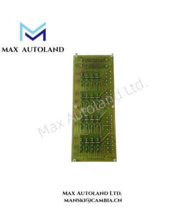
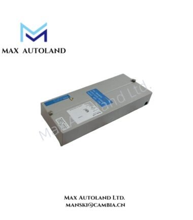
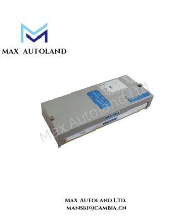
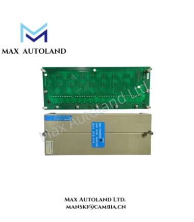
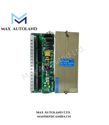
The Honeywell MU-GAIH83, also cataloged as the MU-GAIH83 HLAI/STI Field Termination Assembly, conditions 4-20 mA transmitter signals and routes them to the associated HLAI Input/Output Processor within Honeywell process control architectures. It supports 2-wire and 3-wire transmitters while providing galvanic isolation and loop interface functions.
Hardware Specifications
| Parameter | Specification |
|---|---|
| Model | MU-GAIH83 |
| Brand | Honeywell |
| Origin | Not specified in the supplied data |
| Product Type | High-Level Analog Input / Smart Transmitter Interface FTA |
| Input Signals | 4-20 mA current signals |
| Supported Transmitters | 2-wire and 3-wire transmitters |
| Output Signals | 1-5 VDC to associated HLAI IOP |
| Power Supply | 24 VDC |
| Power Consumption | 1.28 A at 24 VDC with 20 mA on all inputs |
| Power Dissipation | 25.0 W maximum with 20 mA on all inputs |
| Galvanic Isolation | 250 VAC between safe and hazardous sides |
| Maximum Input Voltage | 28 V |
| Maximum Input Current | 93 mA |
| Maximum Input Resistance | 300 ohms |
| Dimensions | Approximately 309 x 124 mm |
| FTA Size | B-size FTA |
| IOP Connectors | Two 50-pin connectors |
| Auxiliary Connector | One 50-pin connector |
| Redundancy Support | Two IOP connections support redundant connection arrangements |
| Status Indicators | Green LED for primary IOP activity; green LED for Galvanic Isolation Module power |
4-20 mA Signal Interface and Galvanic Isolation
The MU-GAIH83 accepts 4-20 mA signals from 2-wire or 3-wire transmitters and converts the input interface to a 1-5 VDC signal for the associated HLAI IOP. Therefore, the FTA performs the field-side signal interface before the control processor receives the conditioned analog value.
The assembly provides 250 VAC galvanic isolation between the safe and hazardous sides. This isolation separates the field signal circuit from the associated control-side interface and limits direct electrical coupling between the two sections.
The specified electrical limits are 28 V maximum input voltage, 93 mA maximum input current, and 300 ohms maximum input resistance. Additionally, the stated power load reaches 1.28 A at 24 VDC when all inputs carry 20 mA signals.
Frequently Asked Questions
Q: What transmitter signals does the MU-GAIH83 accept?
A: The FTA accepts 4-20 mA current signals from 2-wire and 3-wire transmitters.
Q: What signal does the MU-GAIH83 provide to the HLAI IOP?
A: The assembly provides a 1-5 VDC signal to the associated High-Level Analog Input/Output Processor.
Q: Does the MU-GAIH83 provide galvanic isolation?
A: Yes. The supplied specifications state 250 VAC isolation between the safe and hazardous sides.
Field Installation Guidelines
- Verify the MU-GAIH83 model before installation and confirm compatibility with the associated Honeywell HLAI IOP.
- De-energize the applicable circuit before connecting or removing field wiring.
- Connect 4-20 mA transmitter wiring according to the approved system wiring diagram. Maintain correct polarity for current-loop connections.
- Separate analog signal wiring from high-voltage power conductors and high-current switching circuits to reduce electrical interference.
- Route shielded analog cables according to the site’s grounding standard. Avoid creating unintended ground loops through multiple shield termination points.
- Inspect the two 50-pin IOP connectors and the auxiliary 50-pin connector before installation. Ensure that connectors seat correctly and remain mechanically secured.
- Confirm that the field-side electrical values remain within the specified limits of 28 V maximum input voltage, 93 mA maximum input current, and 300 ohms maximum input resistance.
- After wiring, verify transmitter loop continuity and confirm that the associated IOP receives the expected conditioned signal.
- Check both green status indicators after energization. The supplied data identifies one indicator for primary IOP activity and another for Galvanic Isolation Module power.
- For hazardous-area installations, apply the site-approved barrier, grounding, segregation, and certification requirements before energizing the field circuit.


Reviews
There are no reviews yet.