
Overview
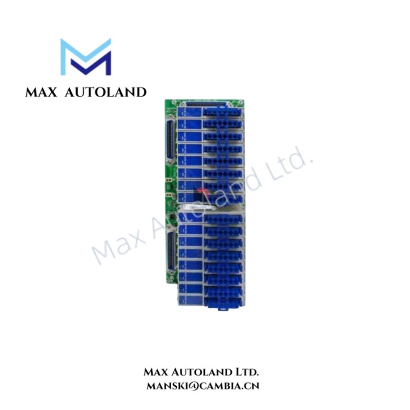
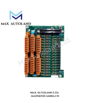
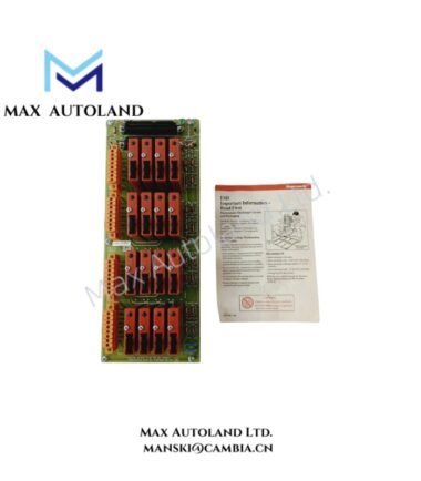
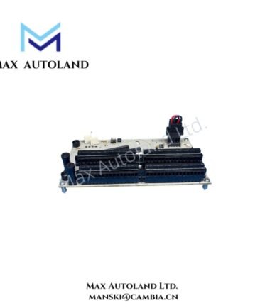
Configured for high-level 4-20 mA signal termination in Honeywell process control systems, the Honeywell MU-GAIH84 (MU-GAIH84 High-Level Analog Input / Smart Transmitter Interface FTA) provides 16 input channels for conventional or smart 2-wire and 3-wire transmitters. The assembly supplies isolated floating DC power and provides 250 Vac isolation between safe and hazardous sides.
Hardware Specifications
| Parameter | Specification |
|---|---|
| Model | MU-GAIH84 |
| Brand | Honeywell |
| Product Type | High-Level Analog Input / Smart Transmitter Interface FTA |
| Dimensions | Approx. 309 mm x 124 mm |
| Operating Temp | Not specified in supplied data |
| Power Consumption | 1.2 A at 24 VDC with 20 mA signal on all inputs |
| Channel Capacity | 16 high-level DC input channels |
| Input Signal | 4-20 mA DC |
| Transmitter Wiring | 2-wire or 3-wire |
| Transmitter Type | Conventional or smart transmitters |
| Open-Circuit Voltage | Maximum 28 V |
| Minimum Voltage at 20 mA | 15 V |
| Power Dissipation | 20.8 W with 20 mA signal on all inputs |
| Isolation Voltage | 250 Vac between safe and hazardous sides |
| Maximum Input Voltage | 28 V |
| Maximum Resistance | 300 ohm |
| Maximum Current | 93 mA |
| Auxiliary PV Output | 1-5 VDC |
| Mounting Type | Standard B-size FTA mounting |
| System Interface | Standard 50-pin connectors |
| I/O Configuration | Supports redundant and non-redundant I/O processors |
4-20 mA Smart Transmitter Interface
The MU-GAIH84 accepts 4-20 mA DC signals from conventional and smart transmitters. It supports both 2-wire and 3-wire transmitter connections, while the input circuit provides isolated floating DC power for field instruments.
The open-circuit voltage reaches a maximum of 28 V, while the specified voltage available at 20 mA is 15 V. Therefore, transmitter loop loading must remain within the stated electrical limits.
Furthermore, the assembly provides 250 Vac isolation between the safe and hazardous sides. This isolation applies to the field interface architecture and must be considered during system wiring and area classification.
The auxiliary connector provides a 1-5 VDC process variable output. This output can serve external monitoring or alarm circuitry where the installation requires a separate PV signal.
Frequently Asked Questions (FAQ)
Q: How many analog input channels does the MU-GAIH84 provide?
A: The assembly provides 16 high-level DC input channels for 4-20 mA transmitter signals.
Q: What transmitter wiring configurations are supported?
A: The MU-GAIH84 supports both 2-wire and 3-wire transmitter connections, including conventional and smart transmitters.
Q: What electrical isolation is specified for the assembly?
A: The supplied specification states 250 Vac isolation between the safe and hazardous sides.
Field Installation Guidelines
- Mount the FTA using the specified standard B-size mounting arrangement and maintain adequate access for field wiring.
- Verify that every transmitter circuit operates within the specified 28 V maximum input voltage and 93 mA maximum current limits.
- Check transmitter loop resistance before commissioning. The specified maximum resistance is 300 ohm.
- Confirm that the transmitter receives at least 15 V at a 20 mA operating condition.
- Route 4-20 mA signal wiring separately from high-voltage power conductors where practical to reduce electrical interference.
- Use appropriate cable shielding and terminate the shield according to the plant grounding standard. Avoid creating unintended ground loops.
- Verify the 250 Vac isolation requirement before connecting circuits between safe-area and hazardous-area equipment.
- Confirm the correct 50-pin connector assignment before connecting the FTA to redundant or non-redundant I/O processors.
- Check the auxiliary 1-5 VDC PV output polarity and wiring before connecting external monitoring equipment.
- Perform loop continuity and signal verification before placing the connected control channel into service.
Reviews
There are no reviews yet.