

Overview
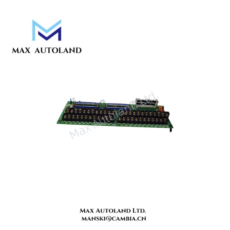
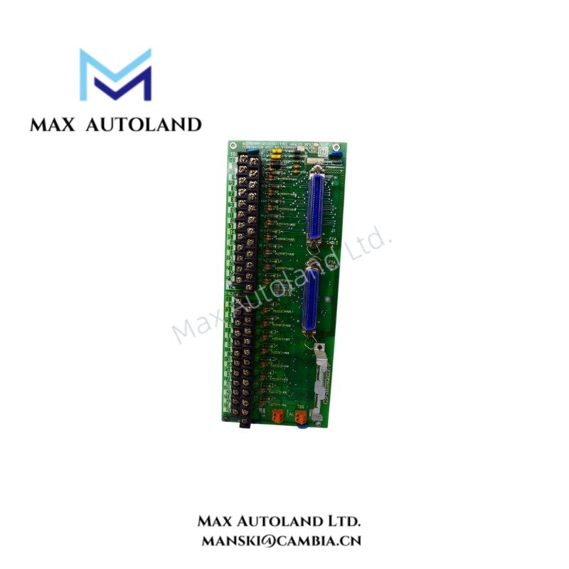
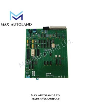
Configured for serial communication interfacing in Honeywell Distributed Control Systems, the Honeywell MC-TSIA12 51303932-478 (MC-TSIA12 Serial Interface Field Termination Assembly) provides direct electrical termination for external serial communication circuits. The assembly supports serial data interfaces including RS-232, RS-422, and RS-485, while providing defined isolation and environmental operating characteristics for industrial control installations.
Hardware Specifications
| Parameter | Specification |
|---|---|
| Model | MC-TSIA12 |
| Full Model / Part Number | 51303932-478 |
| Brand | Honeywell |
| Product Type | Serial Interface Field Termination Assembly |
| System Compatibility | Honeywell Distributed Control Systems |
| Communication Protocol | Modbus RTU / Serial |
| Interface Types | RS-232, RS-422, RS-485 |
| Channels | Typically 1 to 2 channels per I/O Processor (IOP) |
| Maximum Communication Distance | Up to 300 m |
| Baud Rate | Up to 19.2 kbps |
| Data Format | 8 data bits + parity |
| Common Mode Voltage | 250 V RMS continuous |
| Isolation Rating | 1500 V RMS |
| Power Consumption | 1.4 W maximum |
| Operating Temp | -40 deg C to +70 deg C |
| Humidity Range | 5% to 95% non-condensing |
| Approvals / Compliance | CE, UL508, CSA, TUV; conformally coated |
Serial Communication and DCS Instrument Integration
The MC-TSIA12 terminates serial communication circuits between the Honeywell control architecture and external devices. Depending on the configured interface, RS-232, RS-422, or RS-485 wiring can provide the required physical communication path.
For process control applications, the module can therefore support communication with external controllers and intelligent field equipment using serial protocols such as Modbus RTU. The specified 1500 V RMS isolation rating separates the communication interface electrically, while the 250 V RMS continuous common mode specification defines the stated interface tolerance.
Honeywell DCS installations may also combine serial communication equipment with conventional process instrumentation using 4-20 mA HART loop protocols. However, the MC-TSIA12 itself performs serial interface termination rather than direct 4-20 mA analog signal measurement or output.
Frequently Asked Questions
Q: Which physical serial interfaces can the MC-TSIA12 support?
A: The provided specifications identify RS-232, RS-422, and RS-485 interfaces. The applicable wiring configuration depends on the connected communication circuit and system configuration.
Q: What communication distance is specified for the module?
A: The provided data specifies a maximum communication distance of up to 300 m. Actual cable performance depends on the selected interface type, cable characteristics, shielding, grounding, and installation conditions.
Q: Does the MC-TSIA12 provide electrical isolation?
A: Yes. The provided specification lists an isolation rating of 1500 V RMS and a continuous common mode voltage rating of 250 V RMS.
Field Installation Guidelines
Install the MC-TSIA12 only within the designated Honeywell system hardware arrangement and according to the applicable system termination documentation.
Verify the communication interface type before connecting field wiring. RS-232, RS-422, and RS-485 circuits use different electrical arrangements and should not share wiring assumptions.
Route serial communication cables separately from high-current power conductors and switching circuits where practical. In addition, maintain consistent shielding and grounding practices throughout the communication segment.
For RS-485 or RS-422 installations, verify conductor pairing, polarity, and termination requirements against the complete communication network design. Incorrect termination or polarity can prevent stable data exchange.
Inspect the installation environment for moisture, conductive contamination, and mechanical stress. Although the assembly is specified with conformal coating, field wiring and external terminals must also remain within the environmental requirements of the complete installation.
Before energizing the system, verify terminal identification, isolation boundaries, communication settings, and grounding continuity.










Reviews
There are no reviews yet.