
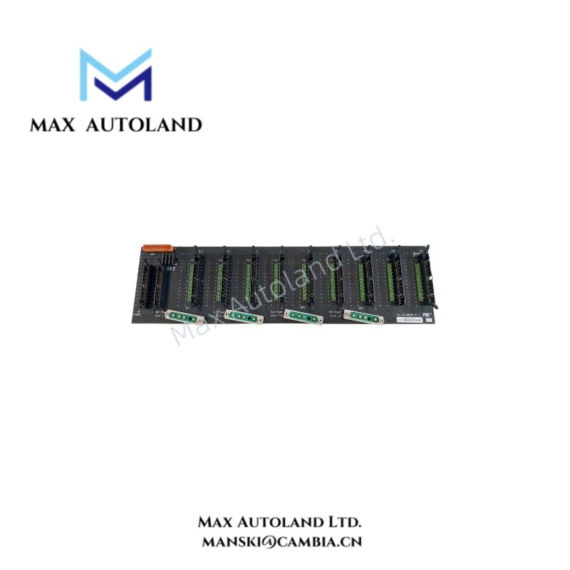
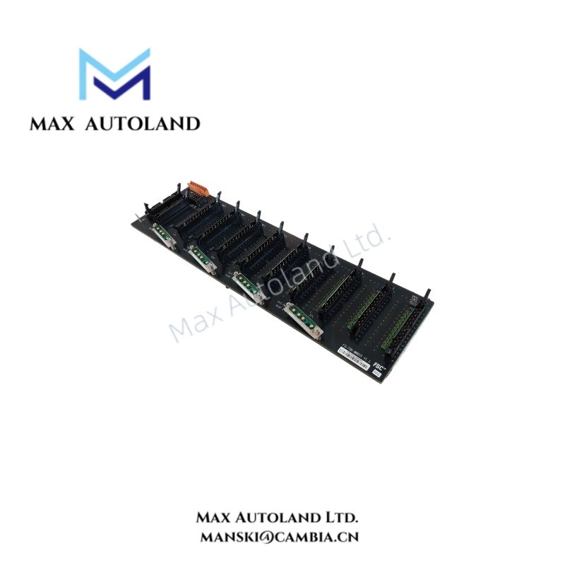
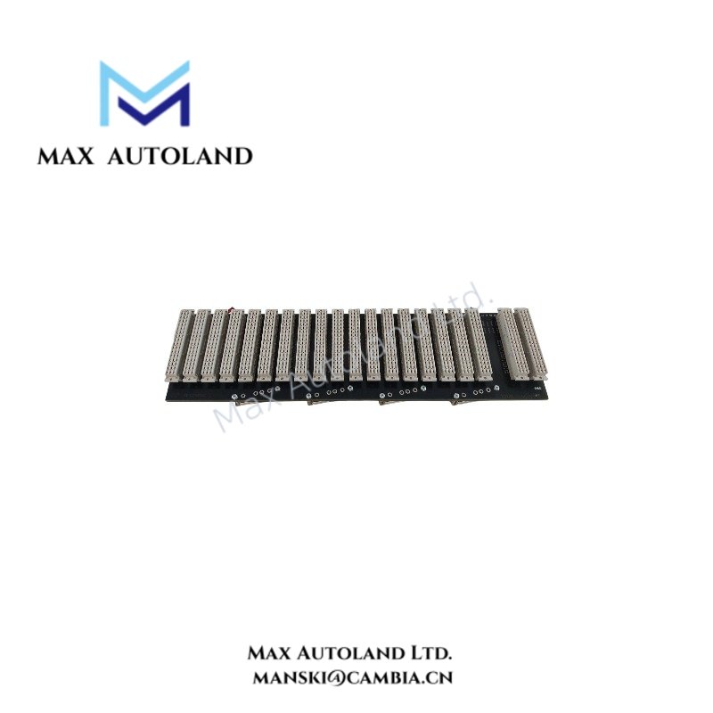
Overview
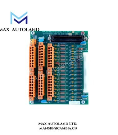
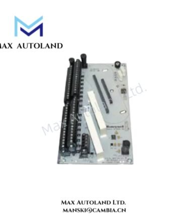
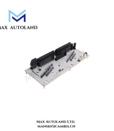
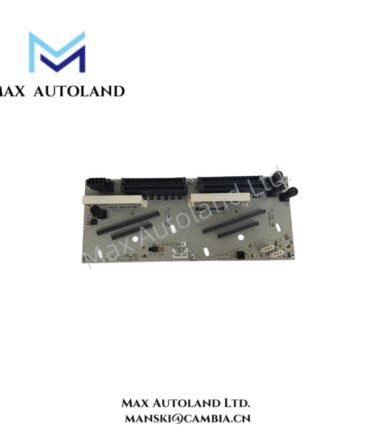
Configured for active impedance matching on a bus termination point, the Honeywell FS-TERM-0002 (FS-TERM Bus Terminator) provides direct electrical termination for controlled signal reflection. It uses a nominal 100 ohm impedance and operates from backplane power with a specified 15 mA current draw at 24 VDC.
Hardware Specifications
| Parameter | Specification |
|---|---|
| Model | FS-TERM-0002 |
| Brand | Honeywell |
| Product Type | Bus Terminator |
| Termination Type | Active impedance matching |
| Nominal Impedance | 100 ohm +/- 1% |
| Power Requirement | Backplane-powered |
| Current Draw | 15 mA at 24 VDC |
| Power Consumption | 0.36 W at 24 VDC, based on specified current draw |
| Isolation Voltage | 500 VDC from backplane |
| Signal Reflection | < -30 dB at 1 GHz |
| Bandwidth | DC to 500 MHz |
| Common Mode Rejection | > 40 dB at 100 MHz |
| Operating Temperature | -40 deg C to +85 deg C |
| Storage Temperature | -50 deg C to +100 deg C |
| Humidity | 5-95% RH, condensing |
| Vibration Resistance | 5 g at 10-500 Hz |
| Weight | 0.2 kg |
| Dimensions | 12 x 8.5 x 6 cm estimated shipping size |
| Origin | USA |
Bus Termination and Signal Integrity
The FS-TERM-0002 applies active impedance matching to the bus termination point. Its 100 ohm nominal impedance maintains the specified electrical load at the termination interface.
The specified signal reflection remains below -30 dB at 1 GHz. The unit also provides a DC to 500 MHz bandwidth and greater than 40 dB common mode rejection at 100 MHz.
The backplane supplies operating power. The specified current draw is 15 mA at 24 VDC. The 500 VDC isolation specification defines the isolation voltage from the backplane.
Frequently Asked Questions
Q: What impedance does the FS-TERM-0002 provide at the bus termination?
A: It provides a nominal 100 ohm impedance with a tolerance of +/- 1%.
Q: How does the FS-TERM-0002 receive operating power?
A: The terminator is backplane-powered and has a specified current draw of 15 mA at 24 VDC.
Q: What signal integrity specifications are provided?
A: The unit specifies less than -30 dB signal reflection at 1 GHz, DC to 500 MHz bandwidth, and greater than 40 dB common mode rejection at 100 MHz.
Field Installation Guidelines
- Install the FS-TERM-0002 at the designated bus termination point specified by the system hardware configuration.
- Confirm that the backplane interface is clean and mechanically secure before installation.
- Verify the bus termination arrangement before energizing the system. Do not add or remove termination hardware without checking the applicable network configuration.
- Keep bus signal wiring separated from high-current power conductors where the installation permits.
- Maintain appropriate cable shielding and grounding practices according to the system wiring design.
- Do not exceed the specified environmental limits of -40 deg C to +85 deg C during operation.
- Protect the module from condensation and contamination when installed in environments approaching the specified 5-95% RH range.
- Verify the backplane connection after installation before applying operating power.





Reviews
There are no reviews yet.