

Overview
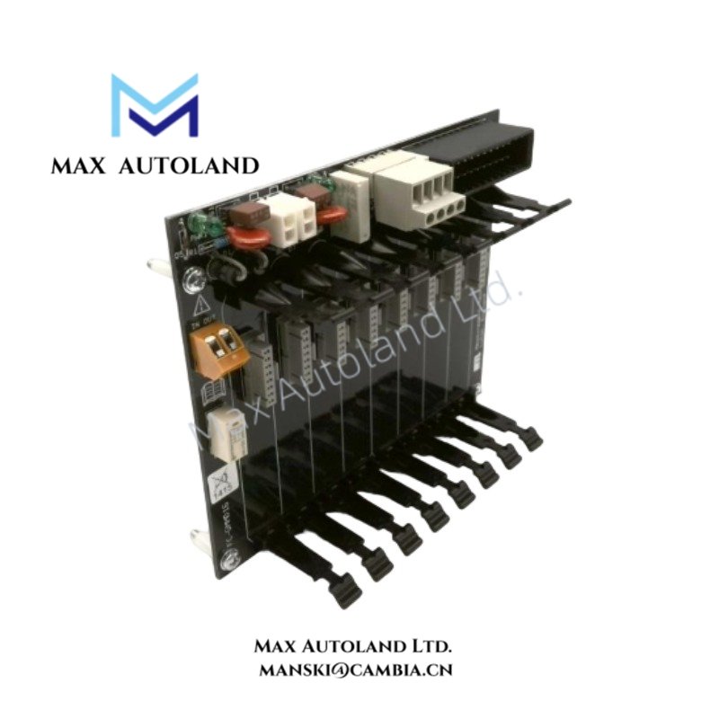
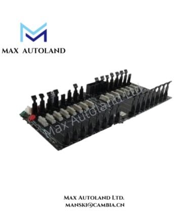
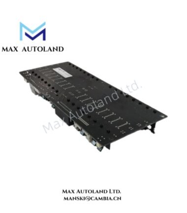
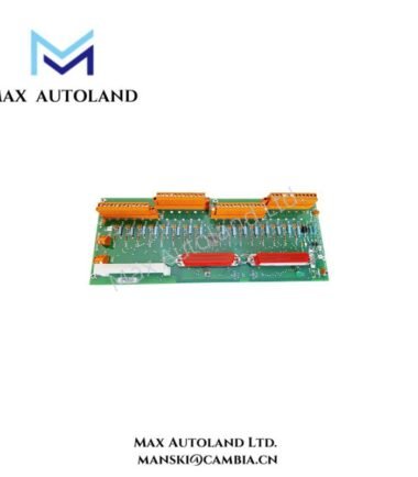
Configured for 24 VDC digital signal acquisition in a Honeywell control or safety system, the Honeywell FC-GMMD16 (FC-GMMD16 Digital Input Module) provides 16 isolated input channels for direct field signal interfacing. Each channel accepts a standard 24 VDC digital input, while galvanic isolation separates field-side signals from the system interface.
Hardware Specifications
| Parameter | Specification |
|---|---|
| Model | FC-GMMD16 |
| Brand | Honeywell |
| Product Type | 16-Channel Digital Input Module / FTA |
| Number of Channels | 16 isolated digital inputs |
| Input Voltage | 24 VDC |
| Input Type | Digital Input |
| Isolation | Channel-to-system galvanic isolation |
| Diagnostics | Built-in self-diagnostics for module health and loop status |
| Certifications | CE, RoHS |
Channel Isolation and Digital Signal Interface
The FC-GMMD16 processes discrete field signals through 16 isolated digital input channels. The 24 VDC input interface provides the electrical threshold for field-side digital states. In addition, channel-to-system galvanic isolation limits direct electrical coupling between field wiring and the system-side interface.
Built-in diagnostics monitor module and loop status. However, the supplied specifications do not define individual diagnostic thresholds, fault response timing, or input current limits.
Frequently Asked Questions
Q: How many digital input channels does the FC-GMMD16 provide?
A: The module provides 16 isolated digital input channels.
Q: What input voltage is specified for the FC-GMMD16?
A: The supplied data specifies 24 VDC digital inputs.
Q: Does the FC-GMMD16 provide galvanic isolation?
A: Yes. The supplied specifications identify channel-to-system galvanic isolation.
Field Installation Guidelines
Install the FC-GMMD16 according to the applicable Honeywell system hardware documentation and cabinet layout requirements.
- Verify that field wiring matches the specified 24 VDC digital input interface before energization.
- Keep digital signal wiring separated from high-voltage power and high-current switching conductors.
- Route field wiring with appropriate strain relief and terminal identification.
- Connect cable shields according to the grounding scheme specified for the host control cabinet.
- Verify channel polarity and field-device states before applying power.
- Confirm diagnostic indications after installation and check each connected input channel individually.
- Do not apply an input voltage outside the specified interface requirements.
- The supplied data does not define hot-swap conditions, terminal assignments, maximum input current, or environmental limits. Verify these parameters in the applicable Honeywell installation documentation before commissioning.






Reviews
There are no reviews yet.