

Overview
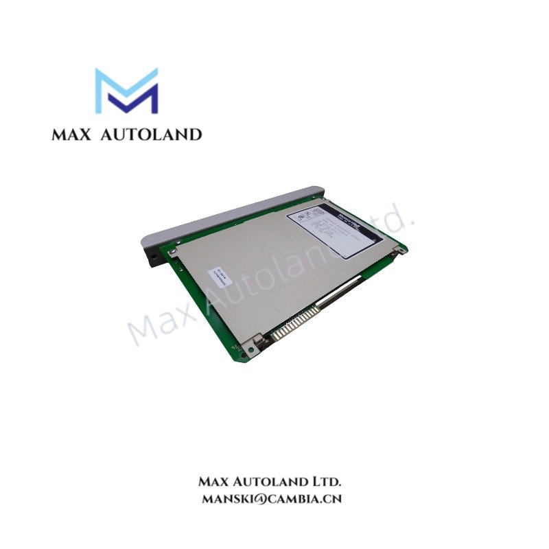
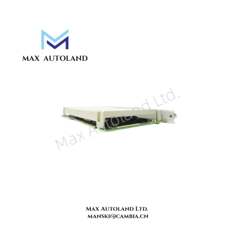
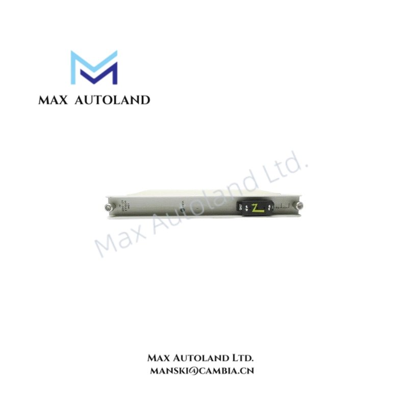
Configured for process hardware monitoring and telemetry validation in Universal Control Network (UCN) networks, the Honeywell 621-0021, also cataloged as the Honeywell 621-0021R Enhanced Diagnostic Module, provides direct physical/electrical execution. This hardware interfaces directly with the UCN backplane architecture to diagnose component status and manage fault reporting routines without introducing processing latencies to primary control tasks.
Hardware Specifications
| Parameter | Specification |
|---|---|
| Model | 621-0021 / 621-0021R |
| Brand | Honeywell |
| Origin | United States |
| Weight | 0.6 kg |
| Dimensions | 3.0 cm x 26.7 cm x 17.3 cm |
| Operating Temp | 0 to 60 degC |
| Power Consumption | 5 VDC via backplane bus |
| Role | Enhanced Diagnostic Module |
| Architecture | Universal Control Network (UCN) |
Channel-to-Channel Isolation and Loop Diagnostics
This Honeywell UCN module incorporates hardware-level channel-to-channel isolation to prevent electrical transients from propagating across adjacent circuit paths. The integrated circuit architecture isolates the diagnostic logic from the field backplane up to 1500 VAC. This isolation protects the processing core when verifying 4-20 mA HART loop protocol parameters and detecting open-circuit or short-circuit anomalies across the network segment. The module continuously samples downstream field buses to ensure impedance levels match configured system limits.
Frequently Asked Questions
Q: Does the 621-0021 module support live insertion and removal during system operation?
A: No. Hot-swap operations are restricted. The UCN chassis must be powered down before extracting or inserting the module to prevent electrical arcing across the backplane gold fingers.
Q: What do the onboard diagnostic status LEDs indicate during initialization?
A: A solid red indicator at startup isolates a hardware internal checksum error during the power-on self-test (POST). A flashing green indicator denotes active, synchronized communication with the UCN backplane.
Field Installation Guidelines
- Ensure the chassis power supply is isolated and verified dead before inserting the 621-0021 into the designated slot.
- Align the module printed circuit board edges with the chassis plastic card guides. Slide the module backward until the dual-lever ejectors engage completely with the backplane connectors.
- Secure the top and bottom retention screws to ensure continuous chassis grounding connection and minimize mechanical vibration drift.
- Maintain a minimum clear distance of 5.0 cm above and below the chassis assembly to allow adequate vertical convection thermal airflow.









Reviews
There are no reviews yet.