
Overview
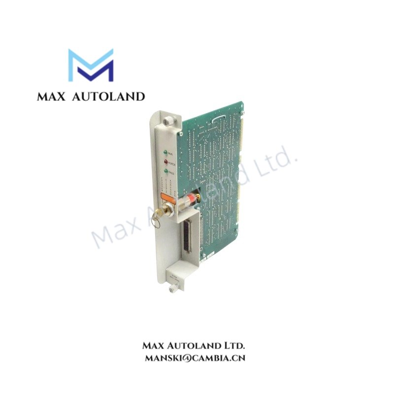
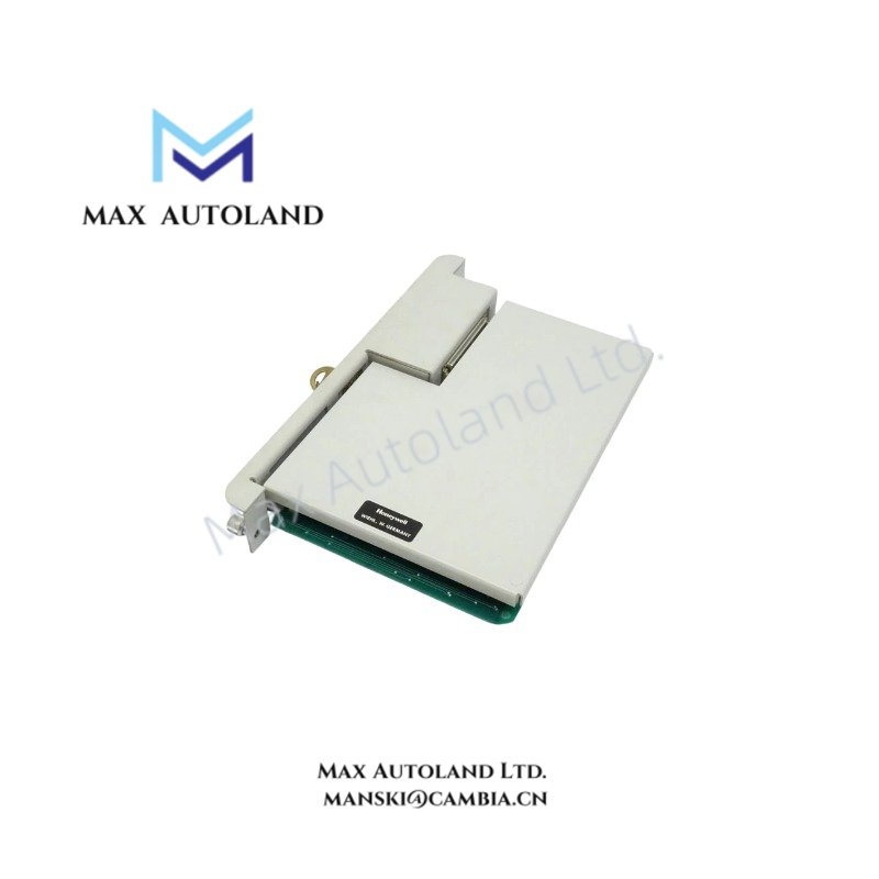
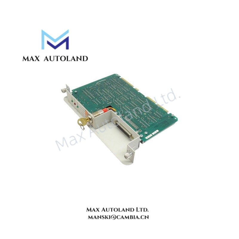
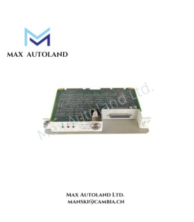
The Honeywell 620-0086, also cataloged as the 620-0086 Parallel Link Driver Module, operates as a dedicated hardware component for high-speed parallel data transmission within Universal Control Network (UCN) platforms. The module executes deterministic physical-layer signaling to interface processor racks with distributed I/O drop locations, ensuring synchronous bus communication.
Hardware Specifications
| Parameter | Specification |
|---|---|
| Model | 620-0086 |
| Brand | Honeywell |
| Module Type | Parallel Link Driver Module |
| Origin | United States |
| Weight | 0.9 kg |
| Dimensions | 3.6 cm x 26.5 cm x 17.5 cm |
| Operating Temp | 0 to 60 degC |
| Power Consumption | 5 VDC at 1.2 A (via backplane) |
| Core Performance Index | Dual-channel physical layer link drivability up to standard distance limits |
Process Control and DCS Instrumentation Implementation
The 620-0086 module incorporates dedicated channel-to-channel isolation circuitry to mitigate ground loop currents across distributed network segments. This isolation barrier prevents transient voltage spikes originating on the physical bus from propagating to the primary controller backplane. The internal serial-to-parallel conversion logic synchronizes data frames with the master clock cycle of the Universal Control Network (UCN), guaranteeing deterministic scan times for interconnected analog loop interfaces and fieldbus bridging units.
Frequently Asked Questions
Q: Does the 620-0086 module support live insertion or hot-swap capabilities during active network operation?
A: No. The module must be powered down along with the hosting chassis before removal or insertion. Inserting the module while the backplane is energized can cause transient data corruption on the parallel link bus and potentially damage the internal CMOS logic.
Q: How is link integrity monitored on the parallel interface?
A: The module utilizes onboard diagnostic LED indicators that map directly to physical link status. Hardware-level parity checking is performed on each data word, and any persistent transmission failure triggers a backplane interrupt to notify the host controller of a link degradation event.
Field Installation Guidelines
- Chassis Power Off: Ensure all power sources to the local housing rack are disconnected before sliding the module into the designated slot guides.
- Shield Grounding: Connect the parallel interface cable shielding directly to the functional earth ground terminal of the enclosure. Do not allow the shield to float, as this introduces electromagnetic interference into the differential signaling paths.
- Securing Mechanisms: Tighten the top and bottom retaining screws to the specified torque rating to maintain structural integrity and a solid grounding connection with the chassis frame.





Reviews
There are no reviews yet.