




Overview
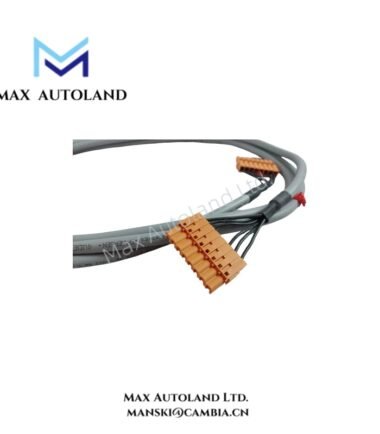
Configured for physical power distribution between the bus bar and I/O chassis, the Honeywell FS-PDC-IOSET (FS-PDC-IOSET Power Distribution Cable Set) provides a direct electrical connection through a 2-pole squeeze-to-release interface and an FM5W5 S female connector.
Hardware Specifications
| Parameter | Specification |
|---|---|
| Model | FS-PDC-IOSET |
| Brand | Honeywell |
| Product Type | Power Distribution Cable Set |
| Origin | USA |
| Weight | 0.55 kg |
| Dimensions | 27 x 25 x 6 cm estimated shipping size |
| Cable Type | CC 600 World 4 x 2.5 mm2 |
| Bus Bar Side | 2-pole Squeeze To Release |
| Release Type | D-TAB-200-STR |
| I/O Chassis Side | FM5W5 S female |
| Connector Housing | Low profile, 90 deg |
| Approvals | UL, CSA; FM pending |
| Operating Temp | -40 deg C to +85 deg C |
| Storage Temp | -40 deg C to +85 deg C |
| Humidity | 5-95% RH, non-condensing |
Power Distribution and Connector Interface
The FS-PDC-IOSET uses a CC 600 World cable construction with four conductors, each sized at 2.5 mm2. The bus bar connection uses a 2-pole squeeze-to-release interface with the D-TAB-200-STR release type.
On the I/O chassis side, the cable terminates in an FM5W5 S female connector. The low-profile 90 deg housing controls the connector orientation at the chassis interface. Therefore, installation should maintain sufficient clearance around the connector body and cable exit.
The supplied specifications identify UL and CSA approvals, while FM approval remains pending. The stated environmental range is -40 deg C to +85 deg C with 5-95% RH non-condensing humidity.
Frequently Asked Questions
Q: What connector is used on the bus bar side of the FS-PDC-IOSET?
A: The bus bar side uses a 2-pole squeeze-to-release connection with the D-TAB-200-STR release type.
Q: What connector terminates the I/O chassis side?
A: The I/O chassis side uses an FM5W5 S female connector with a low-profile, 90 deg housing.
Q: What cable construction does the FS-PDC-IOSET use?
A: The specified cable type is CC 600 World 4 x 2.5 mm2.
Field Installation Guidelines
- Verify the cable model and connector orientation before installation.
- Confirm that the bus bar connection fully engages the D-TAB-200-STR squeeze-to-release mechanism.
- Align the FM5W5 S female connector with the I/O chassis interface before applying insertion force.
- Maintain the specified low-profile 90 deg connector orientation during routing.
- Route the cable away from sharp edges, moving mechanisms, and sources of mechanical abrasion.
- Avoid excessive bending or tensile loading at either connector termination.
- Keep power-distribution wiring physically separated from sensitive signal wiring where the installation layout permits.
- Inspect connector housings and contact surfaces for contamination or mechanical damage before energization.
- Verify conductor continuity and correct polarity according to the applicable system wiring documentation before applying power.










Reviews
There are no reviews yet.