

Overview
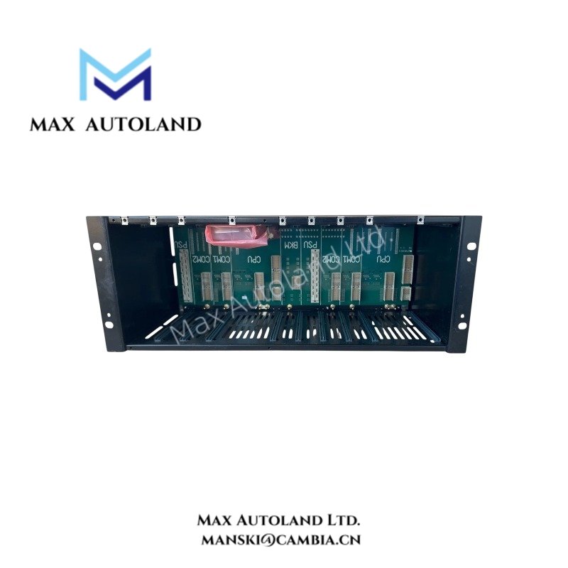
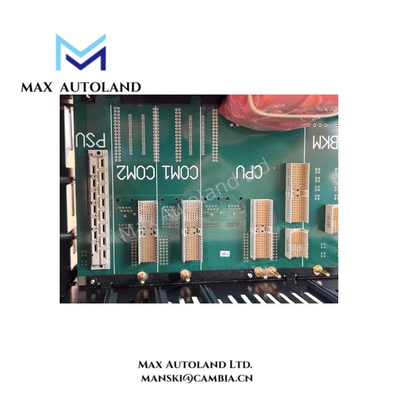
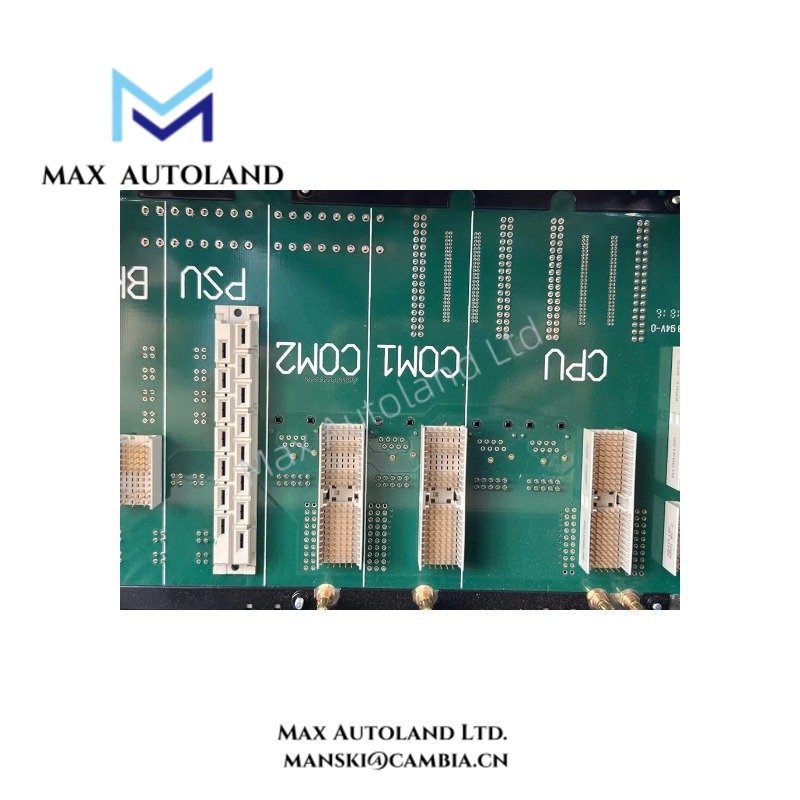
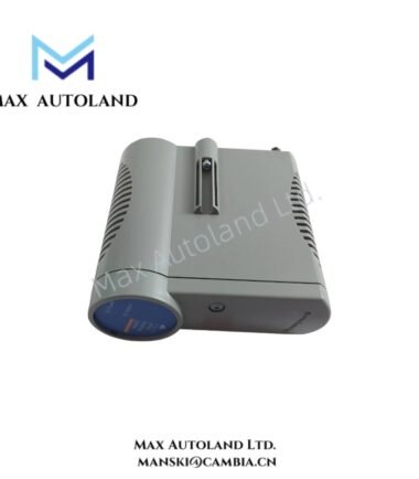
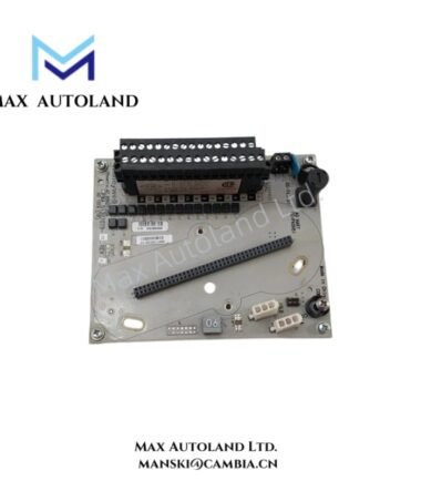
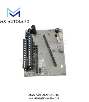
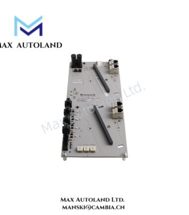
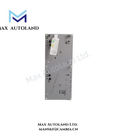
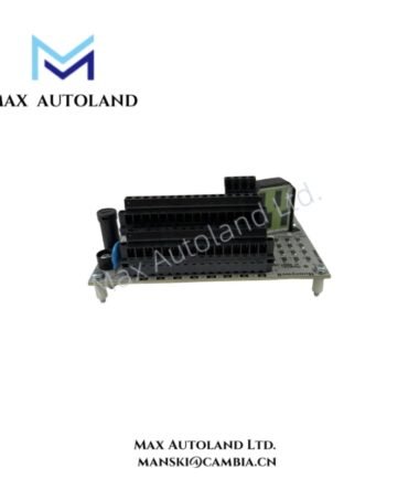
Configured for mounting redundant or non-redundant controllers in a Honeywell Safety Manager system, the Honeywell FS-CPCHAS-0001 (FS-CPCHAS Control Processor Chassis) provides the mechanical platform and internal power distribution required for controller installation. The chassis uses separate 5V-1 and 5V-2 power inputs, each rated at 0.05 A.
Suffix Breakdown & Model Matrix
The supplied documentation identifies FS-CPCHAS-0001 as a complete cataloged model. No additional suffix matrix or option-code breakdown is specified.
Hardware Specifications
| Parameter | Specification |
|---|---|
| Model | FS-CPCHAS-0001 |
| Brand | Honeywell |
| Product Type | Chassis for Control Processor |
| Application | Redundant or non-redundant Controller |
| Origin | USA |
| Weight | 5.84 kg |
| Dimensions | 48.3 x 28 x 17.6 cm estimated shipping size |
| Operating Temp | -40 deg C to +70 deg C |
| Storage Temp | -50 deg C to +85 deg C |
| Humidity | 5-95% RH, condensing |
| Shock Resistance | 30 g, 11 ms half-sine |
| Power Input 5V-1 | 0.05 A |
| Power Input 5V-2 | 0.05 A |
| Approvals | CE, UL, CSA, TUV, FM |
Honeywell Safety Manager Chassis and Power Interface
The FS-CPCHAS-0001 provides the physical chassis structure for controller hardware. Its electrical interface specifies two separate 5 V power inputs: 5V-1 at 0.05 A and 5V-2 at 0.05 A.
For redundant controller configurations, technicians should install the associated controller hardware according to the applicable Honeywell system architecture. The chassis itself does not define controller execution logic or I/O signal conditioning.
The supplied specifications do not define backplane communication speed, hot-swap capability, controller switching time, or channel isolation. Therefore, these parameters should not be assumed for this chassis.
Frequently Asked Questions
Q: Can the FS-CPCHAS-0001 accommodate redundant and non-redundant controller configurations?
A: Yes. The supplied product description identifies the chassis for both redundant and non-redundant controller configurations.
Q: What are the specified power requirements?
A: The chassis specifies 5V-1 at 0.05 A and 5V-2 at 0.05 A.
Q: Does the supplied specification confirm hot-swap operation?
A: No. The provided data does not specify hot-swap capability. Installation and replacement procedures should follow the applicable Honeywell system documentation.
Field Installation Guidelines
Install the FS-CPCHAS-0001 on a mechanically suitable mounting surface that supports the chassis weight and maintains access to connected controller hardware.
Before installation, verify the chassis model and controller configuration. Check the two specified 5 V power connections and maintain correct polarity and terminal identification.
Route power and signal wiring separately where practical to reduce electrical interference. Secure cables to prevent mechanical loading on connectors and terminals.
Use the specified environmental limits when selecting the installation location. The operating range is -40 deg C to +70 deg C, while the storage range is -50 deg C to +85 deg C. Condensing humidity remains within the stated 5-95% RH specification.
Inspect the chassis and connectors for physical damage before energization. After installation, verify mechanical fixation and power connections before installing or starting the associated controller hardware.



Reviews
There are no reviews yet.