

Overview
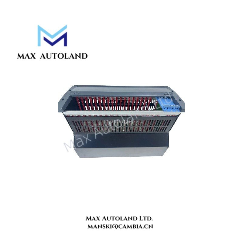
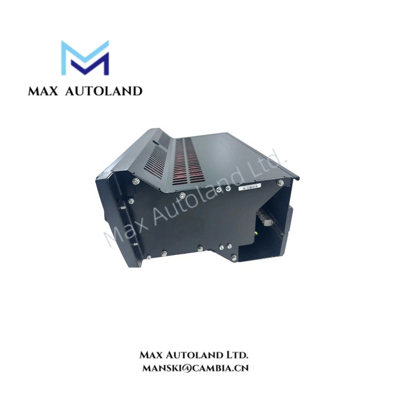
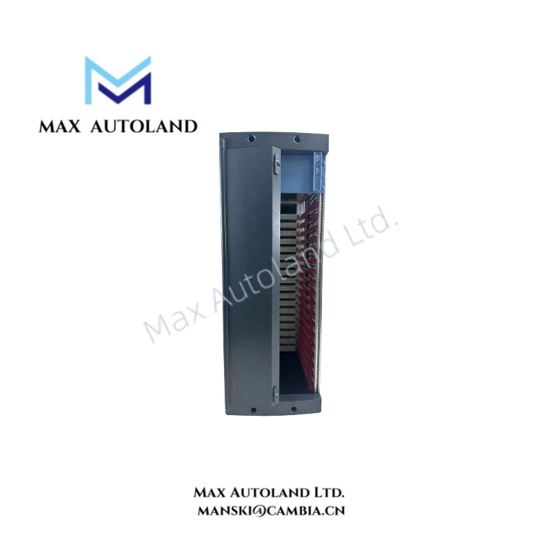
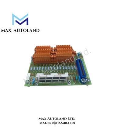
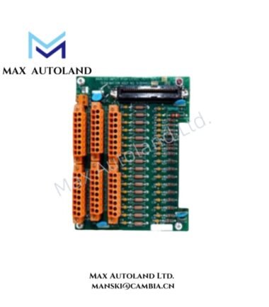
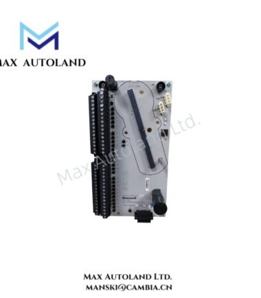
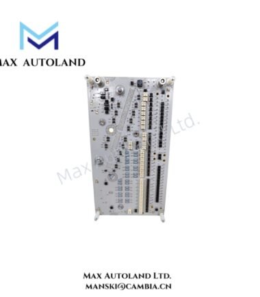
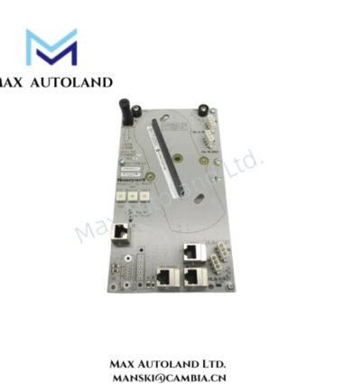
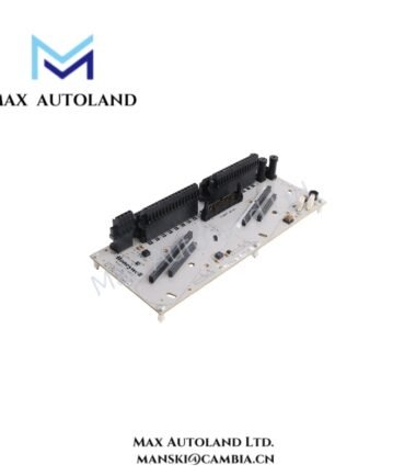
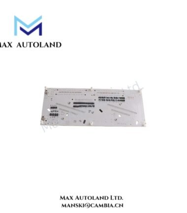
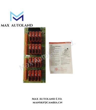
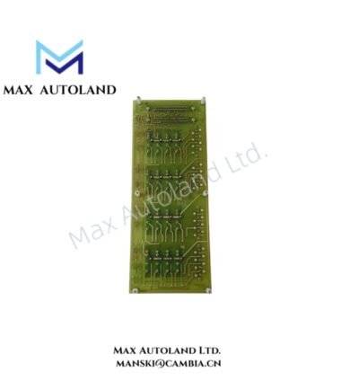
Configured for redundant I/O module mounting and power distribution, the Honeywell FC-IOCHAS-0001R (IOCHAS-0001R I/O Chassis) provides the physical chassis structure for up to 9 pairs of redundant I/O modules. The chassis accepts a 24 VDC input and provides two specified 5 V power feeds for the I/O slot interface.
Hardware Specifications
| Parameter | Specification |
|---|---|
| Model | FC-IOCHAS-0001R |
| Spare Model | IOCHAS-0001R |
| Brand | Honeywell |
| Product Type | I/O Chassis for Redundant Module |
| Origin | USA |
| Weight | 7.6 kg |
| Dimensions | 48.2 x 30 x 22 cm |
| Operating Temp | -40 deg C to +70 deg C |
| Storage Temp | -50 deg C to +85 deg C |
| Humidity | 5-95% RH, condensing |
| Vibration | 5g @ 10-500 Hz, IEC 60068-2-6 |
| Input Voltage | 24 VDC, 18-36 V |
| Power Consumption | 35 W base; 400 W fully loaded |
| Redundant I/O Capacity | Up to 9 pairs |
| 5V-1 Current | 35 mA, IO-0001 slot 20 |
| 5V-2 Current | 35 mA, IO-0001 slot 21 |
| Approvals | CE, UL, CSA, TUV, FM |
| Tariff Code | 8537101190 |
| Estimated Shipping Size | 48.2 x 30 x 22 cm |
Redundant I/O Chassis and Power Distribution
The FC-IOCHAS-0001R provides the mechanical mounting arrangement for paired redundant I/O modules. Each redundant module pair occupies a defined chassis position, with capacity for up to 9 pairs.
The chassis also distributes system power to the I/O interface. The specified 5V-1 and 5V-2 feeds each provide 35 mA for the IO-0001 slot interface. Therefore, installation should maintain the specified power distribution arrangement and avoid unintended loading of these feeds.
For redundant configurations, technicians should verify module placement, connector engagement, and chassis wiring before energizing the 24 VDC input.
Frequently Asked Questions
Q: How many redundant I/O module pairs can the FC-IOCHAS-0001R accommodate?
A: The chassis supports up to 9 pairs of redundant I/O modules.
Q: What input voltage does the chassis require?
A: The specified input is 24 VDC, with an operating input range of 18-36 VDC.
Q: What are the specified 5 V power outputs?
A: The 5V-1 and 5V-2 feeds are each specified at 35 mA and correspond to IO-0001 slots 20 and 21.
Field Installation Guidelines
- Mount the chassis on a mechanically stable structure with sufficient clearance for module insertion and connector access.
- Verify the 24 VDC supply voltage and polarity before connecting the chassis power wiring.
- Install redundant I/O modules in their designated paired positions and verify that each connector is fully engaged.
- Route power wiring separately from high-current switching conductors where practical to reduce electrical interference.
- Keep signal and communication wiring organized and avoid unnecessary parallel routing with motor or high-voltage cables.
- Connect protective earth and chassis grounding according to the applicable Honeywell system installation documentation and site grounding standard.
- Inspect all connectors, terminals, and cable restraints before energization.
- Confirm that the installed module load remains within the specified chassis power consumption limits.
- After power-up, verify the chassis and installed I/O modules for correct status indications before placing the associated control channels into service.



Reviews
There are no reviews yet.