
Overview
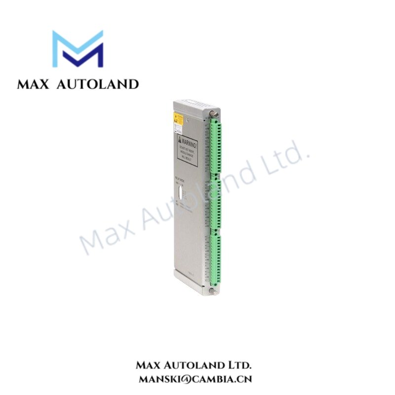
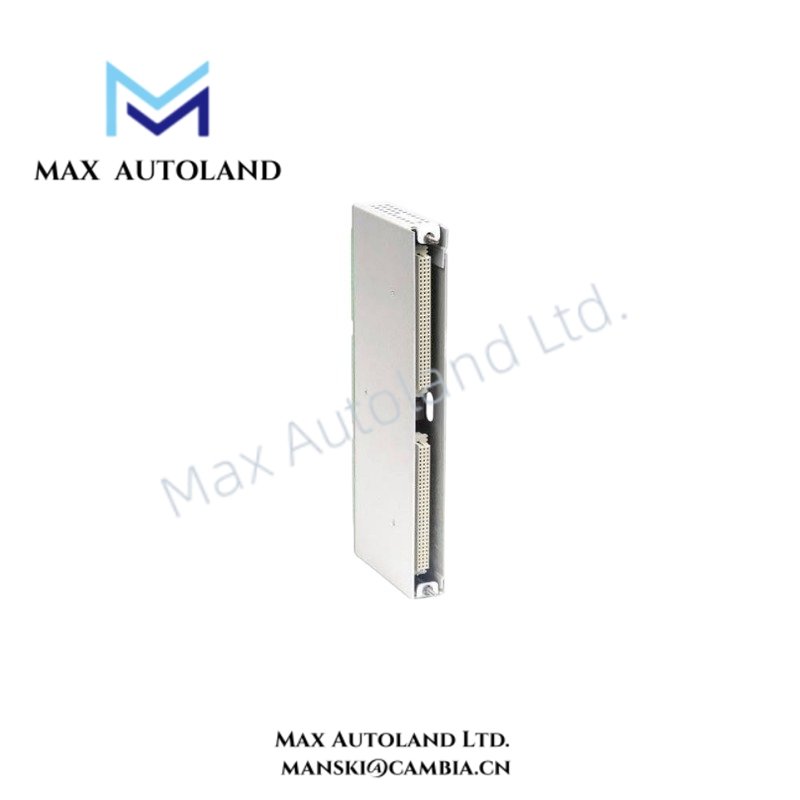
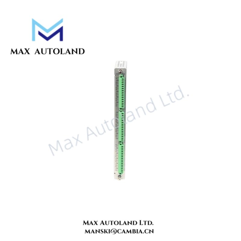
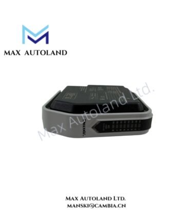
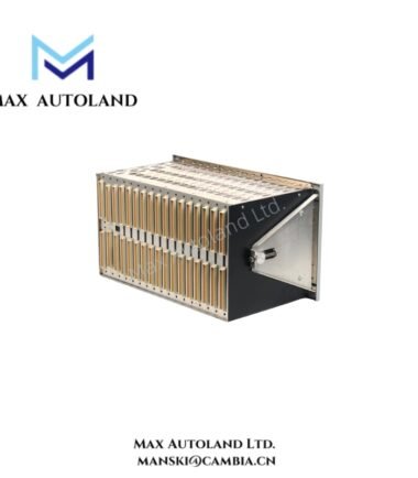
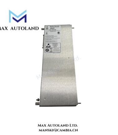
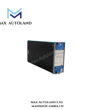
The Bently Nevada 3500/33-01-05, also cataloged as the 3500/33 16-Channel Relay Module, operates as a dedicated hardware component for relay output execution and alarm logic control within the Bently Nevada 3500 Machinery Protection System.
Hardware Specifications
| Parameter | Specification |
|---|---|
| Model | 3500/33-01-05 |
| Brand | Bently Nevada |
| Product Type | 16-Channel Relay Module |
| Origin | USA |
| Weight | Main Module: 0.7 kg; I/O Module: 0.4 kg |
| Dimensions | Main Module: 241 mm x 24.4 mm x 242 mm; I/O Module: 241 mm x 24.4 mm x 99.1 mm |
| Operating Temp | -30 deg C to +65 deg C |
| Storage Temperature | -40 deg C to +85 deg C |
| Humidity | Up to 95%, non-condensing |
| Power Consumption | 5.8 W typical |
| Relay Type | Single-Pole Double-Throw (SPDT) |
| Number of Channels | 16 relay outputs in 4 groups of 4 channels |
| Relay Configuration | Normally Energized (NE) or Normally De-Energized (ND) selectable per group |
| Relay Contact Life | 100,000 cycles at 5 A, 24 VDC or 240 VAC |
| Maximum Switched Current | 5 A |
| DC Resistive Load | 70 W maximum at 24 VDC |
| AC Resistive Load | 1200 VA maximum |
| Arc Suppression | 250 Vrms standard suppressor |
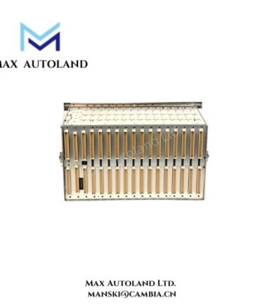
| Rack Position | One full-height front slot and one full-height rear I/O slot |
| Software Compatibility | 3500 Rack Configuration Software V3.3 or later; 3500 Data Acquisition Software V2.40 or later; 3500 Data Display Software V1.40 or later |
Rotor Dynamics and Machinery Protection Signal Control
The 3500/33-01-05 receives alarm status information from monitoring modules installed in the 3500 rack and executes programmed relay actions. Furthermore, it supports Alarm Drive Logic using AND and OR boolean operators with alert states, danger states, Not-OK conditions, and measured channel variables.
For Bently Nevada machinery monitoring applications, relay outputs can operate with TSI-related alarm processing requirements. The module supports system-level event response based on vibration monitoring, position measurement, and rotor dynamics conditions. Additionally, engineers can configure relay behavior according to machine protection logic requirements.
The module operates separately from eddy-current probe scaling and gap voltage validation functions, which are performed by dedicated monitoring modules. However, it can receive processed alarm conditions generated from these measurement channels, including validated -10 VDC gap voltage target states.
Frequently Asked Questions
Q: Can the 3500/33-01-05 relay channels operate with different alarm logic conditions?
A: Yes. Each relay channel supports programmable Alarm Drive Logic using AND and OR operations with rack alarm states, Not-OK conditions, and monitored variables.
Q: Does the 3500/33-01-05 provide direct vibration measurement inputs?
A: No. The module provides relay outputs only. Vibration, position, and speed measurements require dedicated 3500 monitoring modules.
Q: What software is required to configure the relay module?
A: The module requires 3500 Rack Configuration Software V3.3 or later for relay logic setup and parameter configuration.
Field Installation Guidelines
- Install the 3500/33-01-05 in an available full-height slot to the right of the Transient Data Interface (TDI) or Rack Interface Module.
- Install the matching I/O module in the corresponding rear rack position before connecting field wiring.
- Verify relay wiring polarity and contact configuration before applying external control voltage.
- Maintain proper separation between relay signal wiring and high-voltage power cables to reduce electrical interference.
- Connect cable shields according to site grounding standards and avoid multiple-point shield grounding paths.
- Confirm rack configuration settings before enabling machine shutdown or interlock circuits.
- Verify relay state changes through the 3500 software interface before placing the protection system into service.





Reviews
There are no reviews yet.