


Overview
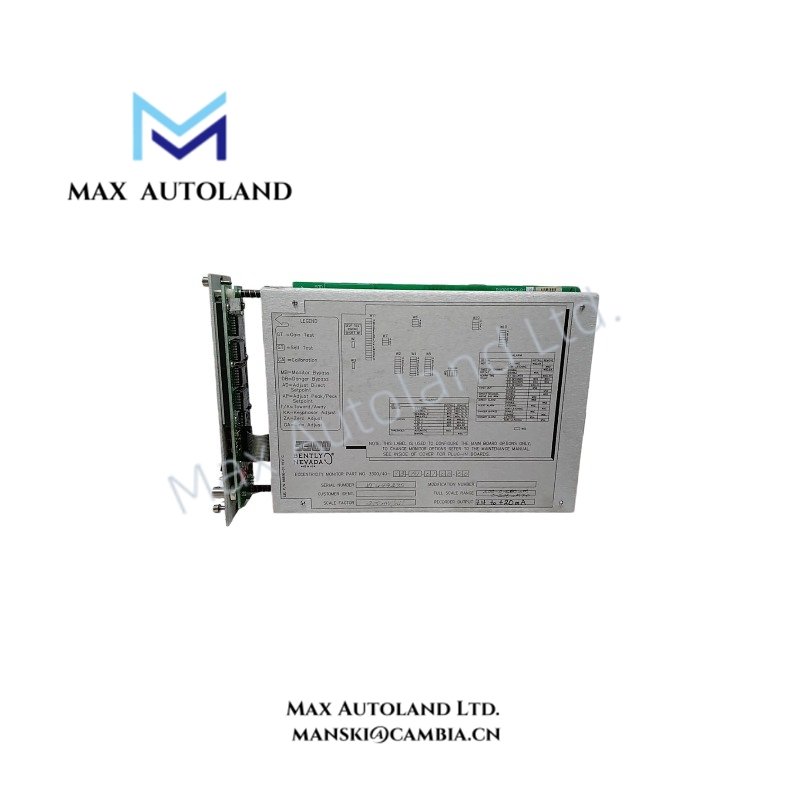
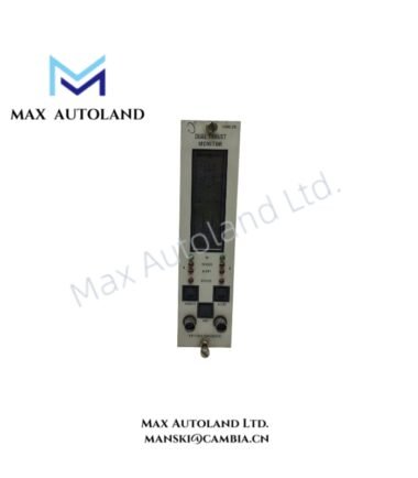
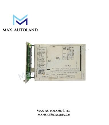
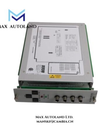
The Bently Nevada 3300/40-13-01-01-00-00, also cataloged as the 3300/40 Eccentricity Monitor Module, operates as a dedicated hardware component for shaft eccentricity measurement within the Bently Nevada 3300 Series Machinery Monitoring System.
Hardware Specifications
| Parameter | Specification |
|---|---|
| Model | 3300/40-13-01-01-00-00 |
| Brand | Bently Nevada |
| Origin | USA |
| Product Type | Eccentricity Monitor Module |
| Series | 3300 Machinery Monitoring System |
| Function | Dual-channel rotor eccentricity and shaft bow measurement |
| Measurement Range | 0 to 500 um pp / 500-0-500 um |
| Input Type | 3300 or 7200 Proximitor System, 200 mV/mil or 8 V/mm |
| Input Channels | Dual-channel proximity probe inputs with Keyphasor input support |
| Signal Scale Factor | Jumper selectable 200 mV/mil / 8 V/mm or 100 mV/mil / 4 V/mm |
| Frequency Response | Direct eccentricity: 0 to 10 Hz; Peak-to-peak eccentricity: 0.017 to 10 Hz |
| Accuracy | +/- 0.33% typical of full scale; +/- 1% maximum at 25 deg C |
| Relay Output | Epoxy-sealed Alert and Danger alarm relays |
| Recorder Output | Configurable +4 to +20 mA, 0 to -10 VDC, or +1 to +5 VDC |
| Buffered Output | Front panel coaxial raw transducer output |
| Operating Temp | 0 deg C to +65 deg C |
| Storage Temp | -40 deg C to +85 deg C |
| Power Consumption | Nominal 1.5 W; up to 7.7 W depending on configuration |
Eddy-Current Probe Scaling and Rotor Dynamics Processing
The 3300/40 module processes displacement signals from Bently Nevada proximity probe systems and applies configured eddy-current probe scaling values for eccentricity calculation. The module evaluates low-frequency shaft position changes caused by rotor bow conditions during turning gear operation, startup, and shutdown sequences.
Furthermore, the module uses Keyphasor reference input signals to correlate shaft position behavior with rotor rotation. This allows the monitoring system to analyze rotor dynamics parameters associated with thermal bow, shaft deformation, and transient mechanical conditions.
The module maintains signal conditioning accuracy by matching the proximity transducer scale factor to the installed probe system. Therefore, correct probe scaling selection directly affects eccentricity measurement accuracy.
Gap Voltage Validation and Signal Integrity
The 3300/40 supports proximity transducer operation with validated gap voltage conditions. Field technicians typically verify probe gap voltage near the -10 VDC target range before commissioning the eccentricity measurement loop.
In addition, the module provides buffered transducer outputs through a front panel coaxial connector. This output allows technicians to perform waveform analysis and confirm probe signal quality without disturbing the primary monitoring circuit.
The module architecture also minimizes measurement errors caused by signal interference through controlled input conditioning and dedicated channel processing.
Frequently Asked Questions
Q: What type of transducers does the Bently Nevada 3300/40-13-01-01-00-00 support?
A: The module accepts signals from Bently Nevada 3300 or 7200 Proximitor Systems with selectable displacement scaling values.
Q: Does the 3300/40 provide direct rotor eccentricity alarm functions?
A: Yes. The module provides Alert and Danger alarm functions through epoxy-sealed relay outputs configured for eccentricity limits.
Q: Can technicians analyze the original proximity probe signal from the module?
A: Yes. The front panel buffered transducer output provides access to the raw signal for diagnostic measurement and waveform analysis.
Field Installation Guidelines
- Install the module in the designated Bently Nevada 3300 rack position according to the system configuration requirements.
- Verify that proximity probe wiring uses appropriate shielded cable routing to reduce electromagnetic interference.
- Connect cable shields according to the site grounding standard and avoid parallel routing with high-voltage power conductors.
- Confirm probe polarity, signal scaling, and gap voltage before enabling eccentricity monitoring.
- Verify Keyphasor input alignment because incorrect reference timing can affect rotor eccentricity analysis.
- Check relay wiring connections before applying machine protection logic to external shutdown circuits.
- Confirm recorder output configuration before connecting external monitoring or data acquisition equipment.




Reviews
There are no reviews yet.