



Overview
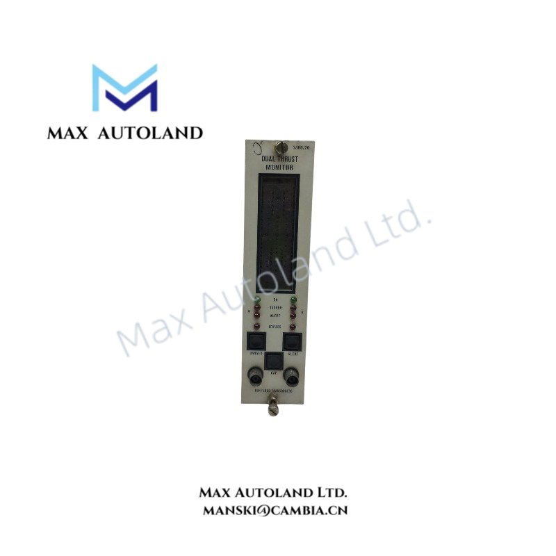
The Bently Nevada 3300/20-12-01-02-00-02, also cataloged as the 3300/20 Dual Thrust Position Monitor, operates as a dedicated hardware component for axial shaft position measurement within the Bently Nevada 3300 Machinery Protection System. It processes two proximity transducer inputs and executes thrust displacement monitoring, alarm logic, and recorder signal output functions.
Hardware Specifications
| Parameter | Specification |
|---|---|
| Model | 3300/20-12-01-02-00-02 |
| Brand | Bently Nevada |
| Product Type | Dual Thrust Position Monitor |
| System Platform | Bently Nevada 3300 Machinery Protection System |
| Origin | USA |
| Weight | Not specified in available technical data |
| Dimensions | 1-slot 3300 rack module format |
| Operating Temp | 0 deg C to +65 deg C |
| Storage Temp | -40 deg C to +85 deg C |
| Relative Humidity | 95% non-condensing |
| Power Consumption | 2.7 W typical from 3300 System Power Supply |
| Input Channels | 2 independent proximity probe channels |
| Input Type | Bently Nevada proximity transducer signals |
| Input Impedance | 10 kOhm |
| Transducer Supply | -24 VDC excitation for Proximitor sensors |
| Measurement Function | Axial shaft displacement and thrust position monitoring |
| Alarm Logic | AND / OR voting for OK, Alert, and Danger conditions |
| Alarm Setpoints | Adjustable Alert and Danger thresholds |
| Recorder Output | 4-20 mA or 0 to -10 VDC per channel |
| Accuracy | +/-1% of full scale range at +25 deg C |
| Relay Output | Programmable Alert and Danger relay contacts |
| Front Panel Indication | LED bargraph or digital meter display with OK, Alert, Danger, and Bypass status |
Eddy-Current Probe Scaling and Gap Voltage Validation
The Bently Nevada 3300/20 applies eddy-current probe scaling methods to convert shaft displacement signals into proportional electrical outputs. The monitor receives proximity probe signals from the 3300 Proximitor system and evaluates axial movement according to calibrated probe sensitivity.
Additionally, the module uses gap voltage validation to confirm probe operating conditions. The system checks the probe bias level, including typical -10 VDC gap voltage targets, to identify probe position errors, cable faults, or Proximitor signal problems. Therefore, the built-in OK circuit logic helps prevent invalid measurements from generating incorrect machinery protection actions.
The monitor also supports rotor dynamics analysis by providing continuous thrust position data for evaluating axial shaft behavior. Furthermore, dual-channel voting logic improves protection decisions by comparing independent measurement paths before initiating alarm conditions.
Frequently Asked Questions
Q: Does the 3300/20-12-01-02-00-02 support dual probe voting logic?
A: Yes. The monitor supports both AND and OR voting configurations for OK, Alert, and Danger alarm processing. Dual probe AND voting can reduce false alarms caused by a single failed measurement path.
Q: What type of transducer signals does the module accept?
A: The module accepts two proximity transducer signals from Bently Nevada 3300 series Proximitor systems for axial shaft position measurement.
Q: Does the module provide external control system signal outputs?
A: Yes. Each monitoring channel provides proportional recorder outputs through 4-20 mA or 0 to -10 VDC signals for connection to external data acquisition or control systems.
Field Installation Guidelines
- Install the module in the designated slot of a Bently Nevada 3300 rack and verify correct backplane connection before system startup.
- Connect proximity probe wiring according to Bently Nevada installation requirements and maintain correct polarity between probe, extension cable, and Proximitor connections.
- Use shielded signal wiring for proximity transducer circuits and connect cable shields according to site grounding practices to reduce electrical interference.
- Verify probe gap voltage before operation to confirm correct mechanical clearance and signal conditioning status.
- Separate low-level proximity signal wiring from high-voltage power cables to minimize electromagnetic coupling.
- Confirm Alert and Danger setpoints against the machine protection logic documentation before placing the monitoring channel into service.
- Check OK status indicators after installation to verify probe, cable, and monitor circuit health.




Reviews
There are no reviews yet.