




Overview
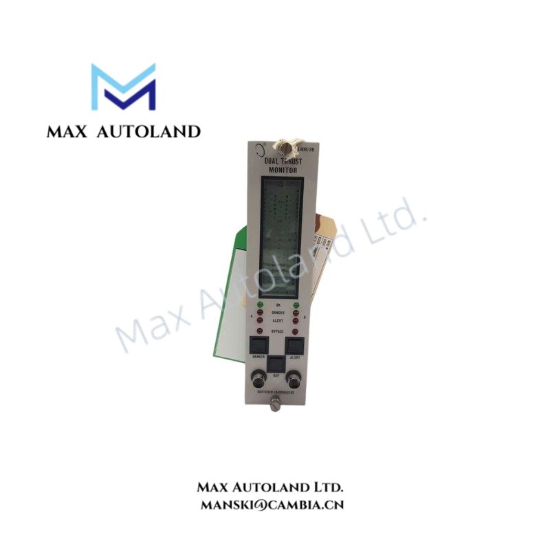
The Bently Nevada 3300/20-12-01-00-00-00, also cataloged as the 3300/20 Dual Thrust Position Monitor, operates as a dedicated hardware component for axial shaft position measurement within the Bently Nevada 3300 Machinery Monitoring System. It processes two independent eddy-current probe signals for thrust bearing clearance monitoring and alarm generation.
Hardware Specifications
| Parameter | Specification |
|---|---|
| Model | 3300/20-12-01-00-00-00 |
| Part Number | 135322-01 |
| Brand | Bently Nevada |
| Product Type | Dual Thrust Position Monitor |
| System Platform | Bently Nevada 3300 Machinery Monitoring System |
| Origin | USA |
| Weight | Approx. 1.0 kg |
| Dimensions | 1 rack position module format for 3300 system rack |
| Operating Temp | 0 deg C to +65 deg C |
| Storage Temp | -40 deg C to +85 deg C |
| Relative Humidity | Up to 95%, non-condensing |
| Power Consumption | 5 W typical |
| Input Channels | 2 independent thrust position channels |
| Input Signal Type | Eddy-current proximity probe input |
| Probe Compatibility | 3300 Series, 7200 Series, 3300 XL Proximitor systems |
| Transducer Supply Voltage | -24 VDC or -18 VDC, user programmable |
| Input Impedance | 10 kOhm |
| Full Scale Range | 1.0 – 0 – 1.0 mm |
| Signal Accuracy | +/- 0.33% of full scale typical |
| Maximum Accuracy Error | +/- 1% at 25 deg C |
| Alarm Setpoint Repeatability | 0.39% of full scale |
| Recorder Output | +4 to +20 mA, 0 to -10 VDC, or +1 to +5 VDC |
| Recorder Output Load | 0 to 600 Ohm |
| Buffered Output Impedance | 100 Ohm |
| Front Panel Interface | Coaxial buffered transducer output connectors |
| Alarm Indication | Alert, Danger, and OK LED status indicators |
| Agency Approval | CSA / NRTL / C |
Eddy-Current Probe Scaling and Rotor Dynamics Monitoring
The 3300/20 module applies Bently Nevada eddy-current probe scaling technology to convert axial displacement signals into calibrated thrust position values. Therefore, the module maintains measurement consistency between probe output voltage and mechanical shaft movement.
The monitor supports 3300 series proximity transducers with standard scaling characteristics and processes dynamic shaft position changes associated with rotor dynamics. Additionally, the dual-channel architecture allows comparison between independent probes installed on the same thrust collar or shaft location.
The module also validates probe operating conditions through gap voltage monitoring. Proper probe setup requires field verification of gap voltage values, including typical Bently Nevada -10 VDC target conditions for eddy-current probe calibration.
Frequently Asked Questions
Q: How many thrust position signals can the 3300/20 monitor process?
A: The module processes two independent thrust position channels. Each channel accepts a compatible Bently Nevada eddy-current proximity probe input.
Q: Does the module support buffered signal access during operation?
A: Yes. The module provides front panel coaxial buffered outputs and rear terminal outputs for diagnostic measurement without disconnecting the monitoring circuit.
Q: Can the module use voting logic for thrust protection applications?
A: Yes. The dual-channel design supports AND voting configurations to reduce false alarms caused by single probe faults or abnormal probe gap conditions.
Field Installation Guidelines
Install the 3300/20 module in an approved Bently Nevada 3300 rack position and verify correct backplane connection before system startup.
Connect proximity probe wiring according to Bently Nevada installation practices. Use shielded signal cables and maintain proper separation from high-current power conductors to reduce electrical interference.
Verify probe polarity, extension cable routing, and Proximitor interface compatibility before applying power. Confirm probe gap voltage values during commissioning and adjust mechanical probe position according to the required thrust clearance measurement range.
Ground cable shields according to site grounding standards. Avoid multiple grounding points that can create unwanted signal loops. After installation, verify OK status indication, channel measurement stability, and alarm setpoint operation through the monitoring system interface.







Reviews
There are no reviews yet.