
Overview
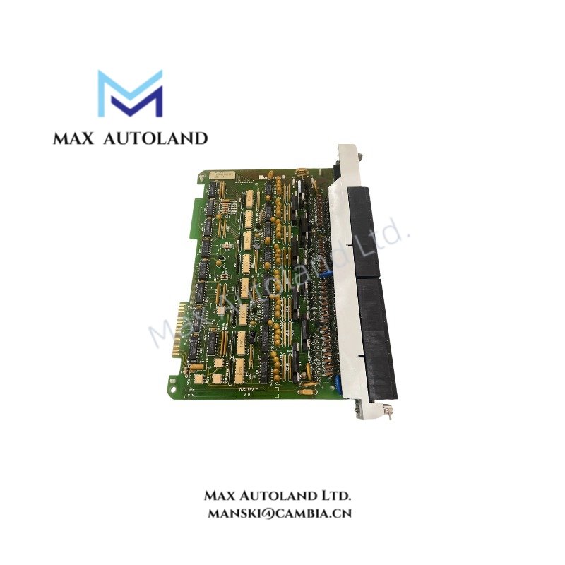
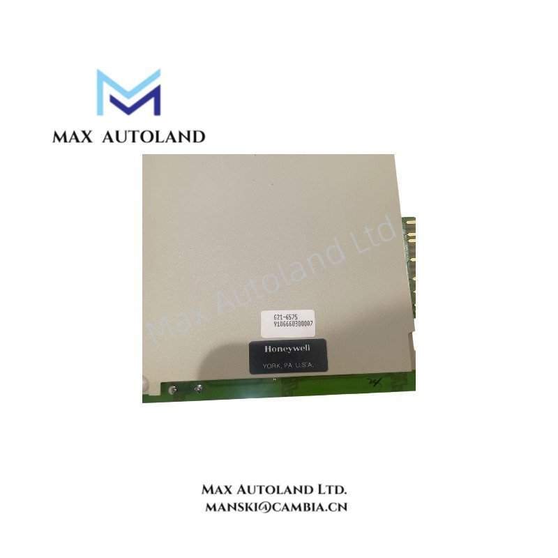
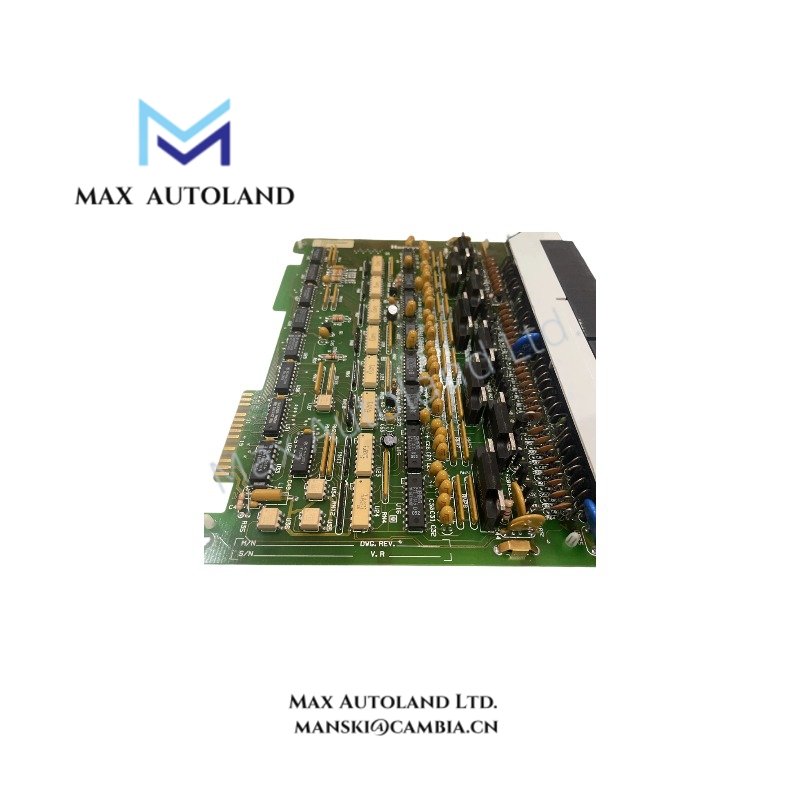
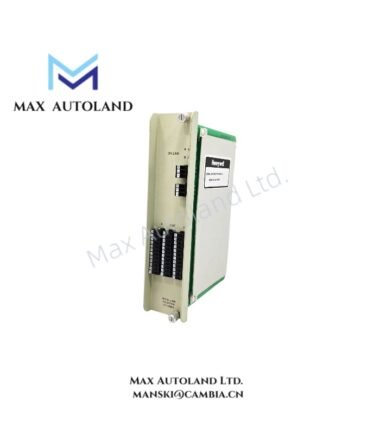
Configured for direct digital output switching in ISSC 600 system, the Honeywell 621-6575 (621-6575R Digital Output Module) provides direct physical/electrical execution. The module operates as a 32 point 24 Vdc output interface for discrete signal actuation within Honeywell IPC ISSC 600 backplane architecture, handling field device energization via isolated channel switching and system-controlled logic states.
Suffix Breakdown & Model Matrix
No validated suffix segmentation data is defined for 621-6575R beyond manufacturer spare designation mapping. No functional decomposition is assumed.
Hardware Specifications
| Parameter | Specification |
|---|---|
| ModelBrand | Honeywell 621-6575 / 621-6575R |
| Weight | 0.5 kg |
| Dimensions | 3.0 cm x 26.7 cm x 16.5 cm |
| OperatingTemp | Not specified |
| PowerConsumption | Not specified |
| Output Channels | 32 point digital output |
| Output Voltage | 24 Vdc |
| System Compatibility | Honeywell IPC ISSC 600 System |
| Module Type | Digital Output Module |
Honeywell Process Signal Execution Characteristics
Within Honeywell IPC ISSC 600 architectures, discrete output modules typically interface with backplane-driven command frames and field termination assemblies. Channel-level switching design supports isolated output staging to minimize cross-channel electrical interaction during simultaneous load actuation. System integration commonly aligns with distributed control configurations utilizing 24 Vdc discrete logic boundaries and rack-based signal routing across industrial I/O strata.
Frequently Asked Questions
Q: Does the 621-6575 support hot-swap removal under live backplane power conditions?
A: Hot-swap capability depends on ISSC 600 rack configuration and backplane design revision. Electrical isolation sequencing must be verified at rack level before insertion or removal.
Q: Are output channels individually isolated on this module?
A: Channel architecture is implemented to support grouped or isolated switching depending on internal board revision and system grounding topology.
Q: What is the typical backplane current loading behavior?
A: Backplane current draw is determined by output state distribution and load energization profile; no fixed consumption value is defined at module specification level.
Field Installation Guidelines
Maintain correct backplane seating alignment prior to insertion to prevent edge connector stress. Ensure all field wiring follows 24 Vdc discrete wiring standards with proper segregation from analog signal routes. Shield termination, where applicable, should be bonded at a single ground reference point to avoid loop formation. Verify output load compatibility before energization to prevent contact overstress under inductive switching conditions.





Reviews
There are no reviews yet.